DK-MAXII-1270N Altera, DK-MAXII-1270N Datasheet - Page 21
DK-MAXII-1270N
Manufacturer Part Number
DK-MAXII-1270N
Description
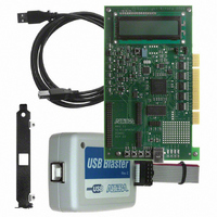
KIT DEV MAXII W/EPM 1270N
Manufacturer
Altera
Series
MAX® IIr
Type
CPLDr
Specifications of DK-MAXII-1270N
Contents
Dev Board, Quartus®II Web Edition, Nios®II Web Edition, Cables, Accessories, Reference Designs and Demos
Silicon Manufacturer
Altera
Core Architecture
CPLD
Core Sub-architecture
MAX
Silicon Core Number
EPM
Silicon Family Name
MAX II
Rohs Compliant
Yes
For Use With/related Products
MAX®II CPLDs
Lead Free Status / RoHS Status
Lead free / RoHS Compliant
Other names
544-2380
Available stocks
Company
Part Number
Manufacturer
Quantity
Price


Altera Corporation
July 2005
f
then the power. Similarly, the current drawn by V
R95 and R99. Using the same technique as described for V
you to calculate the total power being consumed by the MAX II device.
1
On-Board Circuit
The MAX II device current draw is measured across two 0.33 ohm
resistors via a current sense device. The output of this device is fed to an
A/D converter that generates a digital (serial) output to the MAX II
device. The value of this number provides an indication of the current
that is consumed by the MAX II device, allowing you to determine how
much power the MAX II device is consuming.
Refer to the MAX II Development Board Data Sheet and the MAX II
development board schematics for more information about the on-board
circuitry.
Using the Demo
To use this demo, first program the MAX II device with the
LowPowerDemo.pof file in the <install directory>/Examples/
HW/Demos directory. (Refer to
page 2–4
After programming finishes, the LCD will read:
The switches control the operation of this demo:
■
■
■
■
Current Is 24 mA
000 FF’s
Switch 1 = reset
Switch 2 = increase the number of flip-flops that are toggling by 150
Switch 3 = decrease the number of flip-flops that are toggling by 150
Switch 4 = double the rate at which the flip-flops are toggling
Development Kit Version 1.1.0
This circuit uses resistors with a specified variance of 5%, which
means that the power measurement is not precise. This circuit is
provided to give users a general understanding of the MAX II
device power consumption. Users who need a precise power
measurement should remove the resistors and measure the
current with a multimeter across one of the pads where R109
and R113 reside. Users concerned with power consumption
should also consult the Understanding & Evaluating Power in
MAX II Devices chapter of the MAX II Device Handbook.
for details on how to load POF files into the MAX II device.)
MAX II Development Kit Getting Started User Guide
“Programming the MAX II Device” on
CCIO
is measured across
Getting Started
CCINT
allows
2–13
Related parts for DK-MAXII-1270N
Image
Part Number
Description
Manufacturer
Datasheet
Request
R

Part Number:
Description:
KIT DEV MAX V 5M570Z
Manufacturer:
Altera
Datasheet:

Part Number:
Description:
CYCLONE II STARTER KIT EP2C20N
Manufacturer:
Altera
Datasheet:


Part Number:
Description:
CPLD, EP610 Family, ECMOS Process, 300 Gates, 16 Macro Cells, 16 Reg., 16 User I/Os, 5V Supply, 35 Speed Grade, 24DIP
Manufacturer:
Altera Corporation
Datasheet:
Part Number:
Description:
CPLD, EP610 Family, ECMOS Process, 300 Gates, 16 Macro Cells, 16 Reg., 16 User I/Os, 5V Supply, 15 Speed Grade, 24DIP
Manufacturer:
Altera Corporation
Datasheet:
Part Number:
Description:
Manufacturer:
Altera Corporation
Datasheet:
Part Number:
Description:
CPLD, EP610 Family, ECMOS Process, 300 Gates, 16 Macro Cells, 16 Reg., 16 User I/Os, 5V Supply, 30 Speed Grade, 24DIP
Manufacturer:
Altera Corporation
Datasheet:
Part Number:
Description:
High-performance, low-power erasable programmable logic devices with 8 macrocells, 10ns
Manufacturer:
Altera Corporation
Datasheet:
Part Number:
Description:
High-performance, low-power erasable programmable logic devices with 8 macrocells, 7ns
Manufacturer:
Altera Corporation
Datasheet:
Part Number:
Description:
Classic EPLD
Manufacturer:
Altera Corporation
Datasheet:
Part Number:
Description:
High-performance, low-power erasable programmable logic devices with 8 macrocells, 10ns
Manufacturer:
Altera Corporation
Datasheet:
Part Number:
Description:
Manufacturer:
Altera Corporation
Datasheet:
Part Number:
Description:
Manufacturer:
Altera Corporation
Datasheet:
Part Number:
Description:
Manufacturer:
Altera Corporation
Datasheet: