DK-MAXII-1270N Altera, DK-MAXII-1270N Datasheet - Page 13
DK-MAXII-1270N
Manufacturer Part Number
DK-MAXII-1270N
Description
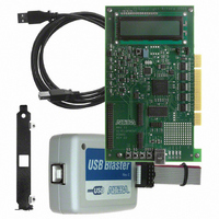
KIT DEV MAXII W/EPM 1270N
Manufacturer
Altera
Series
MAX® IIr
Type
CPLDr
Specifications of DK-MAXII-1270N
Contents
Dev Board, Quartus®II Web Edition, Nios®II Web Edition, Cables, Accessories, Reference Designs and Demos
Silicon Manufacturer
Altera
Core Architecture
CPLD
Core Sub-architecture
MAX
Silicon Core Number
EPM
Silicon Family Name
MAX II
Rohs Compliant
Yes
For Use With/related Products
MAX®II CPLDs
Lead Free Status / RoHS Status
Lead free / RoHS Compliant
Other names
544-2380
Available stocks
Company
Part Number
Manufacturer
Quantity
Price


Altera Corporation
July 2005
Set Up the MAX II Development Board for Programming
1.
2.
3.
Set Up the Quartus II Software for Programming
4.
5.
6.
7.
8.
9.
Make sure the shunt on jumper J8 is connected to pins 1 and 2 (the
two pins closest to the LCD on the board). This supplies power from
the USB cable to the board power plane.
Connect the USB cable from the USB port on your PC to the USB
Type B connector on the MAX II development board.
Connect the ByteBlaster II cable from the parallel port of your PC to
the MAX II board header J2.
1
Launch Quartus II and select Open (File menu).
In the Open dialog box set the Files of Type field to Programming
Files (*.cdf, *.sof, *.pof, *.jam, *.jbc).
Browse to the location of the POF file you want to load into the
MAX II device and open it.
Turn on the three check boxes in the Program/Configure and Verify
columns. See
1
Ensure that the Hardware setup box lists the ByteBlaster II cable in
the box. If it doesn’t, click Hardware Setup and select the
ByteBlaster II cable (you may have to add it using the Add button
before you can select it). Refer to the Quartus Help menu for
assistance in setting up the programming hardware.
Click Start to program the device.
Development Kit Version 1.1.0
The red stripe on the ByteBlaster cable indicates the side
that pin 1 is on.
Note that the CFM refers to the Configuration Flash
Memory—this is the non-volatile portion of the MAX II
device that stores the configuration data and loads it into
the logic portion of the MAX II device. The UFM refers to
the User Flash Memory on the MAX II device. This is
8 Kbits of non-volatile user storage space. For more
information on the MAX II device, the UFM, and the CFM,
refer to the MAX II Device Handbook.
Figure
MAX II Development Kit Getting Started User Guide
2–2.
Getting Started
2–5
Related parts for DK-MAXII-1270N
Image
Part Number
Description
Manufacturer
Datasheet
Request
R

Part Number:
Description:
KIT DEV MAX V 5M570Z
Manufacturer:
Altera
Datasheet:

Part Number:
Description:
CYCLONE II STARTER KIT EP2C20N
Manufacturer:
Altera
Datasheet:


Part Number:
Description:
CPLD, EP610 Family, ECMOS Process, 300 Gates, 16 Macro Cells, 16 Reg., 16 User I/Os, 5V Supply, 35 Speed Grade, 24DIP
Manufacturer:
Altera Corporation
Datasheet:
Part Number:
Description:
CPLD, EP610 Family, ECMOS Process, 300 Gates, 16 Macro Cells, 16 Reg., 16 User I/Os, 5V Supply, 15 Speed Grade, 24DIP
Manufacturer:
Altera Corporation
Datasheet:
Part Number:
Description:
Manufacturer:
Altera Corporation
Datasheet:
Part Number:
Description:
CPLD, EP610 Family, ECMOS Process, 300 Gates, 16 Macro Cells, 16 Reg., 16 User I/Os, 5V Supply, 30 Speed Grade, 24DIP
Manufacturer:
Altera Corporation
Datasheet:
Part Number:
Description:
High-performance, low-power erasable programmable logic devices with 8 macrocells, 10ns
Manufacturer:
Altera Corporation
Datasheet:
Part Number:
Description:
High-performance, low-power erasable programmable logic devices with 8 macrocells, 7ns
Manufacturer:
Altera Corporation
Datasheet:
Part Number:
Description:
Classic EPLD
Manufacturer:
Altera Corporation
Datasheet:
Part Number:
Description:
High-performance, low-power erasable programmable logic devices with 8 macrocells, 10ns
Manufacturer:
Altera Corporation
Datasheet:
Part Number:
Description:
Manufacturer:
Altera Corporation
Datasheet:
Part Number:
Description:
Manufacturer:
Altera Corporation
Datasheet:
Part Number:
Description:
Manufacturer:
Altera Corporation
Datasheet: