DK-MAXII-1270N Altera, DK-MAXII-1270N Datasheet - Page 12
DK-MAXII-1270N
Manufacturer Part Number
DK-MAXII-1270N
Description
KIT DEV MAXII W/EPM 1270N
Manufacturer
Altera
Series
MAX® IIr
Type
CPLDr
Specifications of DK-MAXII-1270N
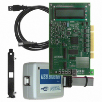
Contents
Dev Board, Quartus®II Web Edition, Nios®II Web Edition, Cables, Accessories, Reference Designs and Demos
Silicon Manufacturer
Altera
Core Architecture
CPLD
Core Sub-architecture
MAX
Silicon Core Number
EPM
Silicon Family Name
MAX II
Rohs Compliant
Yes
For Use With/related Products
MAX®II CPLDs
Lead Free Status / RoHS Status
Lead free / RoHS Compliant
Other names
544-2380
Available stocks
Company
Part Number
Manufacturer
Quantity
Price


Connecting the Cables and Power to the Board & PC
Connecting the
Cables and
Power to the
Board & PC
Programming
the MAX II
Device
2–4
MAX II Development Kit Getting Started User Guide
2.
3.
4.
The MAX II Development Board obtains power from either the USB or
PCI interfaces. The three-pin jumper J8 controls whether power is
obtained via USB or PCI. The board ships with the power control option
set to USB (the shunt on J8 connects pins 1-2). To power the board from
the PCI Edge Connector, the shunt should be moved to pins 2-3.
To use the board outside of a PC chassis, you must connect the USB Type
A-B cable (included with the kit) from your PC to the board. The first time
you connect to your PC, the operating system will notify you that it
“Found New Hardware.” Windows XP automatically installs drivers for
you, while Windows NT and Windows 98 do not. The drivers are only
necessary if you are planning to use your PC to transfer data to and from
the MAX II development board. For more information, refer to
“Reference Design 1: USB Reference Design” on page
ByteBlaster II Cable
The ByteBlaster II cable is used to download new programming files to
the MAX II device. The board supplies power to the ByteBlaster II
download cable. Connect the ByteBlaster II cable’s 10-pin female plug to
the MAX II device JTAG header on the board (J2) and connect the other
end to your PC to configure the MAX II device directly using a POF file.
1
In order to program the MAX II device on the MAX II development
board, you must provide power to the board. The MAX II development
board can be powered via the USB or PCI interfaces. This section assumes
the board is being powered via USB. Refer to
Reference Design” on page 2–26
when the PCI bus is supplying power.
Click Quartus II Web Edition Software.
Follow the on-line instructions to request your license. A license file
is e-mailed to you.
To install your license, refer to “Specifying the License File” in the
Quartus II Installation & Licensing Manual for PCs, included on the
MAX II Development Kit CD-ROM.
Development Kit Version 1.1.0
Align the ByteBlaster II connector so that the red strip is
orientated towards the Altera logo on the board.
for details regarding programming
“Reference Design 3: PCI
2–16.
Altera Corporation
July 2005
Related parts for DK-MAXII-1270N
Image
Part Number
Description
Manufacturer
Datasheet
Request
R

Part Number:
Description:
KIT DEV MAX V 5M570Z
Manufacturer:
Altera
Datasheet:

Part Number:
Description:
CYCLONE II STARTER KIT EP2C20N
Manufacturer:
Altera
Datasheet:


Part Number:
Description:
CPLD, EP610 Family, ECMOS Process, 300 Gates, 16 Macro Cells, 16 Reg., 16 User I/Os, 5V Supply, 35 Speed Grade, 24DIP
Manufacturer:
Altera Corporation
Datasheet:
Part Number:
Description:
CPLD, EP610 Family, ECMOS Process, 300 Gates, 16 Macro Cells, 16 Reg., 16 User I/Os, 5V Supply, 15 Speed Grade, 24DIP
Manufacturer:
Altera Corporation
Datasheet:
Part Number:
Description:
Manufacturer:
Altera Corporation
Datasheet:
Part Number:
Description:
CPLD, EP610 Family, ECMOS Process, 300 Gates, 16 Macro Cells, 16 Reg., 16 User I/Os, 5V Supply, 30 Speed Grade, 24DIP
Manufacturer:
Altera Corporation
Datasheet:
Part Number:
Description:
High-performance, low-power erasable programmable logic devices with 8 macrocells, 10ns
Manufacturer:
Altera Corporation
Datasheet:
Part Number:
Description:
High-performance, low-power erasable programmable logic devices with 8 macrocells, 7ns
Manufacturer:
Altera Corporation
Datasheet:
Part Number:
Description:
Classic EPLD
Manufacturer:
Altera Corporation
Datasheet:
Part Number:
Description:
High-performance, low-power erasable programmable logic devices with 8 macrocells, 10ns
Manufacturer:
Altera Corporation
Datasheet:
Part Number:
Description:
Manufacturer:
Altera Corporation
Datasheet:
Part Number:
Description:
Manufacturer:
Altera Corporation
Datasheet:
Part Number:
Description:
Manufacturer:
Altera Corporation
Datasheet: