OM11048 NXP Semiconductors, OM11048 Datasheet - Page 27
OM11048
Manufacturer Part Number
OM11048
Description
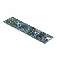
BOARD LPCXPRESSO LPC1343
Manufacturer
NXP Semiconductors
Series
LPCXpressor
Type
MCUr
Datasheet
1.OM11048.pdf
(62 pages)
Specifications of OM11048
Contents
Board, Software
Processor To Be Evaluated
LPC1343
Processor Series
LPC13xx
Interface Type
USB, I2C, UART
Maximum Operating Temperature
+ 85 C
Minimum Operating Temperature
- 40 C
Operating Supply Voltage
3.3 V
Tool Type
Demonstration Board
Core Architecture
ARM
Cpu Core
ARM Cortex M3
Data Bus Width
32 bit
Lead Free Status / RoHS Status
Lead free / RoHS Compliant
For Use With/related Products
LPC1343
Lead Free Status / Rohs Status
Lead free / RoHS Compliant
Other names
568-4947
Available stocks
Company
Part Number
Manufacturer
Quantity
Price

Part Number:
OM11048
Manufacturer:
NXP/恩智浦
Quantity:
20 000
Company:
Part Number:
OM11048Ј¬598
Manufacturer:
PH3
Quantity:
48


NXP Semiconductors
LPC1311_13_42_43
Product data sheet
7.18.5 Boot loader
7.18.6 APB interface
7.18.7 AHB-Lite
7.18.8 External interrupt inputs
7.18.9 Memory mapping control
7.19 Emulation and debugging
The boot loader controls initial operation after reset and also provides the means to
program the flash memory. This could be initial programming of a blank device, erasure
and re-programming of a previously programmed device, or programming of the flash
memory by the application program in a running system.
The boot loader code is executed every time the part is reset or powered up. The loader
can either execute the ISP command handler or the user application code, or, on the
LPC134x, it can program the flash image via an attached MSC device through USB
(Windows operating system only). A LOW level during reset applied to the PIO0_1 pin is
considered as an external hardware request to start the ISP command handler or the USB
device enumeration. The state of PIO0_3 determines whether the UART or USB interface
will be used (LPC134x only).
The APB peripherals are located on one APB bus.
The AHB-Lite connects the instruction (I-code) and data (D-code) CPU buses of the ARM
Cortex-M3 to the flash memory, the main static RAM, and the boot ROM.
All GPIO pins can be level or edge sensitive interrupt inputs. In addition, start logic inputs
serve as external interrupts (see
The Cortex-M3 incorporates a mechanism that allows remapping the interrupt vector table
to alternate locations in the memory map. This is controlled via the Vector Table Offset
Register contained in the NVIC.
The vector table may be located anywhere within the bottom 1 GB of Cortex-M3 address
space. The vector table must be located on a 256 word boundary.
Debug functions are integrated into the ARM Cortex-M3. Serial wire debug is supported.
All information provided in this document is subject to legal disclaimers.
Rev. 3 — 10 August 2010
Section
7.18.1).
32-bit ARM Cortex-M3 microcontroller
LPC1311/13/42/43
© NXP B.V. 2010. All rights reserved.
27 of 62
Related parts for OM11048
Image
Part Number
Description
Manufacturer
Datasheet
Request
R

Part Number:
Description:
NXP Semiconductors designed the LPC2420/2460 microcontroller around a 16-bit/32-bitARM7TDMI-S CPU core with real-time debug interfaces that include both JTAG andembedded trace
Manufacturer:
NXP Semiconductors
Datasheet:

Part Number:
Description:
NXP Semiconductors designed the LPC2458 microcontroller around a 16-bit/32-bitARM7TDMI-S CPU core with real-time debug interfaces that include both JTAG andembedded trace
Manufacturer:
NXP Semiconductors
Datasheet:
Part Number:
Description:
NXP Semiconductors designed the LPC2468 microcontroller around a 16-bit/32-bitARM7TDMI-S CPU core with real-time debug interfaces that include both JTAG andembedded trace
Manufacturer:
NXP Semiconductors
Datasheet:
Part Number:
Description:
NXP Semiconductors designed the LPC2470 microcontroller, powered by theARM7TDMI-S core, to be a highly integrated microcontroller for a wide range ofapplications that require advanced communications and high quality graphic displays
Manufacturer:
NXP Semiconductors
Datasheet:
Part Number:
Description:
NXP Semiconductors designed the LPC2478 microcontroller, powered by theARM7TDMI-S core, to be a highly integrated microcontroller for a wide range ofapplications that require advanced communications and high quality graphic displays
Manufacturer:
NXP Semiconductors
Datasheet:
Part Number:
Description:
The Philips Semiconductors XA (eXtended Architecture) family of 16-bit single-chip microcontrollers is powerful enough to easily handle the requirements of high performance embedded applications, yet inexpensive enough to compete in the market for hi
Manufacturer:
NXP Semiconductors
Datasheet:
Part Number:
Description:
The XA-S3 device is a member of Philips Semiconductors? XA(eXtended Architecture) family of high performance 16-bitsingle-chip microcontrollers
Manufacturer:
NXP Semiconductors
Datasheet:

Part Number:
Description:
The NXP BlueStreak LH75401/LH75411 family consists of two low-cost 16/32-bit System-on-Chip (SoC) devices
Manufacturer:
NXP Semiconductors
Datasheet:
Part Number:
Description:
The NXP LPC3130/3131 combine an 180 MHz ARM926EJ-S CPU core, high-speed USB2
Manufacturer:
NXP Semiconductors
Datasheet:
Part Number:
Description:
The NXP LPC3141 combine a 270 MHz ARM926EJ-S CPU core, High-speed USB 2
Manufacturer:
NXP Semiconductors
Part Number:
Description:
The NXP LPC3143 combine a 270 MHz ARM926EJ-S CPU core, High-speed USB 2
Manufacturer:
NXP Semiconductors

Part Number:
Description:
The NXP LPC3152 combines an 180 MHz ARM926EJ-S CPU core, High-speed USB 2
Manufacturer:
NXP Semiconductors
Part Number:
Description:
The NXP LPC3154 combines an 180 MHz ARM926EJ-S CPU core, High-speed USB 2
Manufacturer:
NXP Semiconductors

Part Number:
Description:
Standard level N-channel enhancement mode Field-Effect Transistor (FET) in a plastic package using NXP High-Performance Automotive (HPA) TrenchMOS technology
Manufacturer:
NXP Semiconductors
Datasheet: