AT91SAM9260-EK Atmel, AT91SAM9260-EK Datasheet - Page 32
AT91SAM9260-EK
Manufacturer Part Number
AT91SAM9260-EK
Description
KIT EVAL FOR AT91SAM9260
Manufacturer
Atmel
Series
AT91SAM Smart ARMr
Type
MCUr
Datasheets
1.AT91SAM9260-EK.pdf
(47 pages)
2.AT91SAM9260-EK.pdf
(39 pages)
3.AT91SAM9260-EK.pdf
(10 pages)
Specifications of AT91SAM9260-EK
Contents
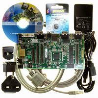
Evaluation Board, Parallel Cable and CD-ROM
Processor To Be Evaluated
AT91SAM9260
Data Bus Width
32 bit
Interface Type
RS-232, Ethernet, USB
Core
ARM 9
Silicon Manufacturer
Atmel
Core Architecture
ARM
Core Sub-architecture
ARM926EJ-S
Silicon Core Number
AT91SAM9260
Silicon Family Name
ARM
Kit Contents
Board, Cables, CD, Power Supply
Rohs Compliant
Yes
For Use With/related Products
AT91SAM9260
Lead Free Status / RoHS Status
Lead free / RoHS Compliant


Note:
10.2.1
10.2.1.1
10.2.1.2
10.3
32
Setting AIC, SYSC, UHP and IRQ0-2 bits in the clock set/clear registers of the PMC has no effect.
Peripheral Signal Multiplexing on I/O Lines
AT91SAM9260
Peripheral Interrupts and Clock Control
System Interrupt
External Interrupts
Table 10-1.
The System Interrupt in Source 1 is the wired-OR of the interrupt signals coming from:
The clock of these peripherals cannot be deactivated and Peripheral ID 1 can only be used
within the Advanced Interrupt Controller.
All external interrupt signals, i.e., the Fast Interrupt signal FIQ or the Interrupt signals IRQ0 to
IRQ2, use a dedicated Peripheral ID. However, there is no clock control associated with these
peripheral IDs.
The AT91SAM9260 features 3 PIO controllers (PIOA, PIOB, PIOC) that multiplex the I/O lines of
the peripheral set.
Each PIO Controller controls up to 32 lines. Each line can be assigned to one of two peripheral
functions, A or B.
define how the I/O lines of the peripherals A and B are multiplexed on the PIO Controllers. The
two columns “Function” and “Comments” have been inserted in this table for the user’s own
comments; they may be used to track how pins are defined in an application.
Note that some peripheral functions which are output only might be duplicated within both
tables.
The column “Reset State” indicates whether the PIO Line resets in I/O mode or in peripheral
mode. If I/O appears, the PIO Line resets in input with the pull-up enabled, so that the device is
maintained in a static state as soon as the reset is released. As a result, the bit corresponding to
the PIO Line in the register PIO_PSR (Peripheral Status Register) resets low.
If a signal name appears in the “Reset State” column, the PIO Line is assigned to this function
and the corresponding bit in PIO_PSR resets high. This is the case of pins controlling memories,
in particular the address lines, which require the pin to be driven as soon as the reset is
released. Note that the pull-up resistor is also enabled in this case.
Peripheral ID
29
30
31
• the SDRAM Controller
• the Debug Unit
• the Periodic Interval Timer
• the Real-time Timer
• the Watchdog Timer
• the Reset Controller
• the Power Management Controller
AT91SAM9260 Peripheral Identifiers (Continued)
Table 10-2 on page
Peripheral Mnemonic
AIC
AIC
AIC
33,
Table 10-3 on page 34
Peripheral Name
Advanced Interrupt Controller
Advanced Interrupt Controller
Advanced Interrupt Controller
and
Table 10-4 on page 35
6221JS–ATARM–17-Jul-09
External Interrupt
IRQ0
IRQ1
IRQ2
Related parts for AT91SAM9260-EK
Image
Part Number
Description
Manufacturer
Datasheet
Request
R

Part Number:
Description:
MCU, MPU & DSP Development Tools KICKSTART KIT FOR AT91SAM9 PLUS
Manufacturer:
IAR Systems

Part Number:
Description:
DEV KIT FOR AVR/AVR32
Manufacturer:
Atmel
Datasheet:

Part Number:
Description:
INTERVAL AND WIPE/WASH WIPER CONTROL IC WITH DELAY
Manufacturer:
ATMEL Corporation
Datasheet:
Part Number:
Description:
Low-Voltage Voice-Switched IC for Hands-Free Operation
Manufacturer:
ATMEL Corporation
Datasheet:
Part Number:
Description:
MONOLITHIC INTEGRATED FEATUREPHONE CIRCUIT
Manufacturer:
ATMEL Corporation
Datasheet:
Part Number:
Description:
AM-FM Receiver IC U4255BM-M
Manufacturer:
ATMEL Corporation
Datasheet:
Part Number:
Description:
Monolithic Integrated Feature Phone Circuit
Manufacturer:
ATMEL Corporation
Datasheet:
Part Number:
Description:
Multistandard Video-IF and Quasi Parallel Sound Processing
Manufacturer:
ATMEL Corporation
Datasheet:
Part Number:
Description:
High-performance EE PLD
Manufacturer:
ATMEL Corporation
Datasheet:
Part Number:
Description:
8-bit Flash Microcontroller
Manufacturer:
ATMEL Corporation
Datasheet:
Part Number:
Description:
2-Wire Serial EEPROM
Manufacturer:
ATMEL Corporation
Datasheet: