DV164101 Microchip Technology, DV164101 Datasheet - Page 70
DV164101
Manufacturer Part Number
DV164101
Description
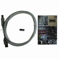
KIT DEV PICKIT1 FLASH 8/14PIN
Manufacturer
Microchip Technology
Series
PICkit™ 1r
Type
MCUr
Specifications of DV164101
Contents
PIC Kit 1 Circuit Board, CD-ROMs, USB Interface Cable and Booklet
Processor To Be Evaluated
PIC12F675
Interface Type
USB
Silicon Manufacturer
Microchip
Core Architecture
PIC
Core Sub-architecture
PIC12, PIC16
Silicon Core Number
PIC12F, PIC16F
Silicon Family Name
PIC12F6xx, PIC16F6xx
Rohs Compliant
NA
Lead Free Status / RoHS Status
Lead free / RoHS Compliant
For Use With/related Products
Microchip's 8-14 Pin FLASH Microcontrollers
For Use With
AC164122 - BOARD DAUGHT PICTAIL SD/MMC CARDAC164120 - BOARD SIGNAL ANALYSIS PICKIT
Lead Free Status / Rohs Status
Lead free / RoHS Compliant
Other names
DV164101R
DV164101R
DV164101R
Available stocks
Company
Part Number
Manufacturer
Quantity
Price
Company:

Part Number:
DV164101
Manufacturer:
Microchip Technology
Quantity:
135


PICkit
C.9
DS40051D-page 66
LESSON 7 – FREQUENCY COUNTING WITH TIMER1 GATE
™
1 Flash Starter Kit User’s Guide
This program introduces the concept of auto-calibration of the PIC12F6XX internal RC
oscillator using a known reference frequency. The PIC12F6XX has an internal RC
oscillator capable of being calibrated to ±1%.
This lesson covers the following:
• How to set up and use the Timer1 gate peripheral
• How to calibrate the PIC12F6XX internal RC oscillator
• Useful applications that use the concepts presented in this lesson
• Files needed to customize source code for the application
C.9.1
This program takes advantage of the TIMER1 gate peripheral onboard the PIC12F6XX
for auto-calibration of the PIC12F6XX device. A 2.5 kHz reference signal is connected
to pin GP4/Timer1Gate input on the PIC12F6XX device.
The PIC12F6XX internal RC oscillator has the capability to run at 4 MHz ±1%.
Using Timer1Gate is advantageous because it can eliminate busy waiting on the PIC
microcontroller. Using Timer1Gate allows the hardware to manage capturing of the
reference signal low-edge pulse width, while allowing the PIC12F6XX to process other
events for a given amount of time. The time will depend on the period of the signal
being measured. In this case, there is a 2.5 kHz reference signal. This allows 400 s
to go and process something else before we would need to read TIMER1 for a
measurement.
C.9.2
In this program, GP0 is used to output a test signal. If the PIC12F6XX internal RC
oscillator is calibrated, the test signal will be a 5 kHz square wave. In addition, the
program uses the GP3 push button input to select calibration mode. To turn on the
2.5 kHz fixed frequency source, select the box from the Board Controls area in the
PICkit 1 Flash Starter Kit control panel. See Figure C-19 through Figure C-22 for
program flowcharts.
C.9.3
This program could be useful in the following applications:
1. High volume production environment.
2. Battery applications could use on-board calibration to recalibrate the internal RC
3. Applications that are exposed to varying voltage and temperature ranges could
oscillator as the battery voltage drops.
have intelligent on-board recalibration.
Design
Implementation
Applications
2004 Microchip Technology Inc.
Related parts for DV164101
Image
Part Number
Description
Manufacturer
Datasheet
Request
R

Part Number:
Description:
Manufacturer:
Microchip Technology Inc.
Datasheet:
Part Number:
Description:
Manufacturer:
Microchip Technology Inc.
Datasheet:
Part Number:
Description:
Manufacturer:
Microchip Technology Inc.
Datasheet:
Part Number:
Description:
Manufacturer:
Microchip Technology Inc.
Datasheet:
Part Number:
Description:
Manufacturer:
Microchip Technology Inc.
Datasheet:
Part Number:
Description:
Manufacturer:
Microchip Technology Inc.
Datasheet:
Part Number:
Description:
Manufacturer:
Microchip Technology Inc.
Datasheet:
Part Number:
Description:
Manufacturer:
Microchip Technology Inc.
Datasheet: