DV164101 Microchip Technology, DV164101 Datasheet - Page 62
DV164101
Manufacturer Part Number
DV164101
Description
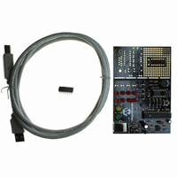
KIT DEV PICKIT1 FLASH 8/14PIN
Manufacturer
Microchip Technology
Series
PICkit™ 1r
Type
MCUr
Specifications of DV164101
Contents
PIC Kit 1 Circuit Board, CD-ROMs, USB Interface Cable and Booklet
Processor To Be Evaluated
PIC12F675
Interface Type
USB
Silicon Manufacturer
Microchip
Core Architecture
PIC
Core Sub-architecture
PIC12, PIC16
Silicon Core Number
PIC12F, PIC16F
Silicon Family Name
PIC12F6xx, PIC16F6xx
Rohs Compliant
NA
Lead Free Status / RoHS Status
Lead free / RoHS Compliant
For Use With/related Products
Microchip's 8-14 Pin FLASH Microcontrollers
For Use With
AC164122 - BOARD DAUGHT PICTAIL SD/MMC CARDAC164120 - BOARD SIGNAL ANALYSIS PICKIT
Lead Free Status / Rohs Status
Lead free / RoHS Compliant
Other names
DV164101R
DV164101R
DV164101R
Available stocks
Company
Part Number
Manufacturer
Quantity
Price
Company:

Part Number:
DV164101
Manufacturer:
Microchip Technology
Quantity:
135


PICkit
DS40051D-page 58
™
1 Flash Starter Kit User’s Guide
C.6.2
This lesson uses the PIC12F675 and demonstrates an interrupt based analog-to-
digital conversion. TMR0 is set up with a prescaler of 4, thus creating an interrupt
roughly every 1 ms. With every TMR0 interrupt, either the LED display routine is
serviced (see Lesson 3) or the A/D routine is serviced depending on the flag that tog-
gles with every interrupt. Noise is generated on V
Therefore, to reduce noise in the A/D process, either a new A/D conversion is done or
the display is updated, but not simultaneously. The A/D interrupt source is not used
because the service interval (2 ms) is much longer than the conversion period of 22 s.
The A/D module requires at least 4 s for the sample capacitor to charge between
acquisitions, but the program allows for about 2 ms. The result of the A/D is 10 bits,
even though only the eight most significant bits are displayed on the LEDs. The result
is left justified (ADFM = 0) and the most significant byte is written to the LEDREGISTER
to be displayed. The ANSEL register specifies which of the general purpose I/O pins
are to be configured as analog inputs to the A/D module. In this case, the potentiome-
ter's output serves as the input to AN0.
Figure C-12 shows the source code files for the assembly and C projects respectively.
FIGURE C-12:
Analog-to-Digital Converter Lesson
ASSEMBLY AND C SOURCE CODE FILES
DD
when the LEDs are updated.
2004 Microchip Technology Inc.
Related parts for DV164101
Image
Part Number
Description
Manufacturer
Datasheet
Request
R

Part Number:
Description:
Manufacturer:
Microchip Technology Inc.
Datasheet:
Part Number:
Description:
Manufacturer:
Microchip Technology Inc.
Datasheet:
Part Number:
Description:
Manufacturer:
Microchip Technology Inc.
Datasheet:
Part Number:
Description:
Manufacturer:
Microchip Technology Inc.
Datasheet:
Part Number:
Description:
Manufacturer:
Microchip Technology Inc.
Datasheet:
Part Number:
Description:
Manufacturer:
Microchip Technology Inc.
Datasheet:
Part Number:
Description:
Manufacturer:
Microchip Technology Inc.
Datasheet:
Part Number:
Description:
Manufacturer:
Microchip Technology Inc.
Datasheet: