DV164101 Microchip Technology, DV164101 Datasheet - Page 61
DV164101
Manufacturer Part Number
DV164101
Description
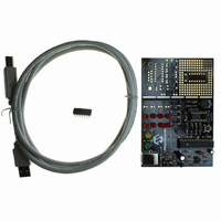
KIT DEV PICKIT1 FLASH 8/14PIN
Manufacturer
Microchip Technology
Series
PICkit™ 1r
Type
MCUr
Specifications of DV164101
Contents
PIC Kit 1 Circuit Board, CD-ROMs, USB Interface Cable and Booklet
Processor To Be Evaluated
PIC12F675
Interface Type
USB
Silicon Manufacturer
Microchip
Core Architecture
PIC
Core Sub-architecture
PIC12, PIC16
Silicon Core Number
PIC12F, PIC16F
Silicon Family Name
PIC12F6xx, PIC16F6xx
Rohs Compliant
NA
Lead Free Status / RoHS Status
Lead free / RoHS Compliant
For Use With/related Products
Microchip's 8-14 Pin FLASH Microcontrollers
For Use With
AC164122 - BOARD DAUGHT PICTAIL SD/MMC CARDAC164120 - BOARD SIGNAL ANALYSIS PICKIT
Lead Free Status / Rohs Status
Lead free / RoHS Compliant
Other names
DV164101R
DV164101R
DV164101R
Available stocks
Company
Part Number
Manufacturer
Quantity
Price
Company:

Part Number:
DV164101
Manufacturer:
Microchip Technology
Quantity:
135


C.6
2004 Microchip Technology Inc.
LESSON 4 – ANALOG-TO-DIGITAL CONVERTERS AND COMPARATORS
This lesson is broken up into two programs which demonstrate how to use the
analog-to-digital converter, the comparator and the internal voltage reference. The first
program set is comp.asm (written in assembly) and comp.c (written in C). This program
shows the very basic implementation of using the comparator with the internal voltage
reference. The second program set is atod.asm (written in assembly) and atod.c
(written in C). This program uses the LED display library to show the value of the
analog-to-digital (A-D) converter.
C.6.1
For this lesson, the comparator is configured as a dedicated comparator driving the
GP2 pin directly. With <CM2:CM0> = 101, the comparator has multiplexed inputs.
GP0/CIN+ is selected as the input to the V
potentiometer the one input. The internal voltage reference is used as the other input
to the comparator on V
reference, and the logic is setup (CINV = 1) such that the output is high when the input
voltage is higher than the reference. LED3 is driven directly by the comparator and is
lit when the output of the module is high. To light D3, you must configure RA4 (GPIO4)
and RA2 (GPIO2) as digital outputs via the TRIS register, RA4 is set low and RA2 is
driven directly by the comparator without additional software overhead. The remaining
I/O's are configured as high impedance inputs.
The internal voltage reference is essentially a variable resistor based voltage divider
between V
reference to be 0.5 V
By stepping through the different voltage reference settings, a basic-low resolution
analog-to-digital converter can be implemented.
The comparator module has seven different modes. Three of the modes can drive an
output pin directly. The software can monitor the output directly or create an interrupt
on change. Bits CMIE and PEIE must be set to enable the comparator interrupt which
can be used to wake the device from SLEEP.
Figure C-11 shows the project setup for the assembly and C projects.
FIGURE C-11:
Note:
Comparator Lesson
DD
The schematics, as shown in Appendix A, display the 14-pin device pinout.
This is compatible with 8-pin devices.
and V
SS
ASSEMBLY AND C PROJECT SETUP
DD
. Use the low range mode (VRR = 1) and set the internal
IN
by selecting <VR3:VR0> = 1100, thus C
+. The module compares the potentiometer voltage with the
IN
- by setting CIS = 1, thus making the analog
VREF
DS40051D-page 57
= V
DD
*(12/24).
Related parts for DV164101
Image
Part Number
Description
Manufacturer
Datasheet
Request
R

Part Number:
Description:
Manufacturer:
Microchip Technology Inc.
Datasheet:
Part Number:
Description:
Manufacturer:
Microchip Technology Inc.
Datasheet:
Part Number:
Description:
Manufacturer:
Microchip Technology Inc.
Datasheet:
Part Number:
Description:
Manufacturer:
Microchip Technology Inc.
Datasheet:
Part Number:
Description:
Manufacturer:
Microchip Technology Inc.
Datasheet:
Part Number:
Description:
Manufacturer:
Microchip Technology Inc.
Datasheet:
Part Number:
Description:
Manufacturer:
Microchip Technology Inc.
Datasheet:
Part Number:
Description:
Manufacturer:
Microchip Technology Inc.
Datasheet: