DV164101 Microchip Technology, DV164101 Datasheet - Page 57
DV164101
Manufacturer Part Number
DV164101
Description
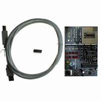
KIT DEV PICKIT1 FLASH 8/14PIN
Manufacturer
Microchip Technology
Series
PICkit™ 1r
Type
MCUr
Specifications of DV164101
Contents
PIC Kit 1 Circuit Board, CD-ROMs, USB Interface Cable and Booklet
Processor To Be Evaluated
PIC12F675
Interface Type
USB
Silicon Manufacturer
Microchip
Core Architecture
PIC
Core Sub-architecture
PIC12, PIC16
Silicon Core Number
PIC12F, PIC16F
Silicon Family Name
PIC12F6xx, PIC16F6xx
Rohs Compliant
NA
Lead Free Status / RoHS Status
Lead free / RoHS Compliant
For Use With/related Products
Microchip's 8-14 Pin FLASH Microcontrollers
For Use With
AC164122 - BOARD DAUGHT PICTAIL SD/MMC CARDAC164120 - BOARD SIGNAL ANALYSIS PICKIT
Lead Free Status / Rohs Status
Lead free / RoHS Compliant
Other names
DV164101R
DV164101R
DV164101R
Available stocks
Company
Part Number
Manufacturer
Quantity
Price
Company:

Part Number:
DV164101
Manufacturer:
Microchip Technology
Quantity:
135


C.5
2004 Microchip Technology Inc.
LESSON 3 – INTERRUPTS
This program demonstrates how to use the Timer0 and pin change interrupts onboard
the PIC12F6XX. In addition, the program illustrates how the PIC12F6XX is multiplexing
the LED's fast enough to give the visual representation that the LED's are all on at the
same time when in fact the LED's are lit individually. Finally, this program uses the
interrupt on-pin change to detect and debounce a button push which changes the rate
at which the LEDs are flashed.
This lesson covers the following topics:
• How to flash LEDs on the PICkit 1 Flash Starter Kit board
• How to use Timer0 and pin change interrupts on the PIC12F6XX
• How to turn a source code file into a library file for easy reuse
• Useful applications that can use the concepts presented in this lesson
• Files needed to customize the source code for the application
C.5.1
One of the challenges of using an 8-pin PIC microcontroller is having enough pins for
a robust application. The PICkit 1 Flash Starter Kit utilizes design tips and tricks to get
the most out of the 8/14-pin PIC microcontroller devices. In particular, a 12-LED array
is implemented on the PICkit 1 Flash Starter Kit by using only 4 pins. In this lesson, only
8 LED's are implemented. See Table C-1 for LED multiplexing. Also, see “TIP #2
Input/Output Multiplexing”, in the “Microchip Tips 'n Tricks 8-pin Flash PIC
controller” booklet (DS44040) for more details on LED multiplexing.
TABLE C-1:
C.5.2
The lesson utilizes interrupts to make the LED operation transparent to the main
program. The main program writes the value 0xFF to the LEDREGISTER. This flashes
8 LEDs on the PICkit 1 Flash Starter Kit board. In order to flash 4 LEDs, for example,
write 0x0F into the LEDREGISTER. The interrupt service routine uses a Timer0
interrupt for updating the LED array. A GP3 pin change interrupt detects a button push.
The Timer0 prescaler is adjusted and changes the amount of time it takes for a Timer0
interrupt to happen. This gives the visual representation that the LEDs are all on at the
same time, or sequencing.
This lesson introduces the intlib library. The intlib library contains the core functions for
flashing the LEDs and debouncing the GP3 push button. The intlib library contains the
functions Display and Debounce. The library also contains the general purpose
register, LEDREGISTER, to flash LEDs. See Section C.9.5, “Modifying the Source
Code”, for more information on the required files needed to build this project in MPLAB
IDE. Also, see the source code files for additional comments on the implementation.
For a high-level flowchart, see Figure C-10.
Legend:
GP4
GP5
GP2
GP1
PIN
LOW
D0
HI
Z
Z
HI => Logic 1, LOW => Logic 0 and Z => TRISIO = 1
Design
Implementation
LOW
D1
HI
Z
Z
LED MULTIPLEXING TRUTH TABLE
LOW
D2
HI
Z
Z
LOW
D3
HI
Z
Z
LOW
D4
HI
Z
Z
LOW
D5
HI
Z
Z
LOW
D6
HI
Z
Z
LOW
D7
HI
Z
Z
LOW
D8
HI
Z
Z
LOW
D9
HI
Z
Z
DS40051D-page 53
LOW
®
D10
HI
Z
Z
Micro-
LOW
D11
HI
Z
Z
Related parts for DV164101
Image
Part Number
Description
Manufacturer
Datasheet
Request
R

Part Number:
Description:
Manufacturer:
Microchip Technology Inc.
Datasheet:
Part Number:
Description:
Manufacturer:
Microchip Technology Inc.
Datasheet:
Part Number:
Description:
Manufacturer:
Microchip Technology Inc.
Datasheet:
Part Number:
Description:
Manufacturer:
Microchip Technology Inc.
Datasheet:
Part Number:
Description:
Manufacturer:
Microchip Technology Inc.
Datasheet:
Part Number:
Description:
Manufacturer:
Microchip Technology Inc.
Datasheet:
Part Number:
Description:
Manufacturer:
Microchip Technology Inc.
Datasheet:
Part Number:
Description:
Manufacturer:
Microchip Technology Inc.
Datasheet: