EVAL-ADT7467EB Analog Devices Inc, EVAL-ADT7467EB Datasheet - Page 31
EVAL-ADT7467EB
Manufacturer Part Number
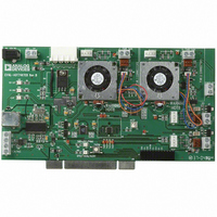
EVAL-ADT7467EB
Description
BOARD EVALUATION FOR ADT7467
Manufacturer
Analog Devices Inc
Series
dBCool®r
Datasheet
1.EVAL-ADT7467EB.pdf
(80 pages)
Specifications of EVAL-ADT7467EB
Sensor Type
Temperature
Sensing Range
-40°C ~ 120°C
Interface
SMBus (2-Wire/I²C)
Sensitivity
±1.5°C
Voltage - Supply
3 V ~ 5.5 V
Embedded
No
Utilized Ic / Part
ADT7467
Lead Free Status / RoHS Status
Contains lead / RoHS non-compliant


Fan TACH Limit Registers
The fan TACH limit registers are 16-bit values consisting of two
bytes.
Reg. 0x54 TACH1 minimum low byte = 0xFF default
Reg. 0x55 TACH1 minimum high byte = 0xFF default
Reg. 0x56 TACH2 minimum low byte = 0xFF default
Reg. 0x57 TACH2 minimum high byte = 0xFF default
Reg. 0x58 TACH3 minimum low byte = 0xFF default
Reg. 0x59 TACH3 minimum high byte = 0xFF default
Reg. 0x5A TACH4 minimum low byte = 0xFF default
Reg. 0x5B TACH4 minimum high byte = 0xFF default
Fan Speed Measurement Rate
The fan TACH readings are normally updated once every
second.
When set, the FAST bit (Bit 3) of Configuration Register 3
(Reg. 0x78) updates the fan TACH readings every 250 ms.
If a fan is powered directly from 5 V or 12 V and is not driven by
a PWM channel, its associated dc bit in Configuration Register 3
should be set. This allows TACH readings to be taken on a
continuous basis for fans connected directly to a dc source. For
optimal results, the associated dc bit should always be set when
using 4-wire fans.
Calculating Fan Speed
Assuming a fan with two pulses per revolution (and two pulses
per revolution being measured), fan speed is calculated by
where Fan TACH Reading is the 16-bit fan tachometer reading.
Example:
TACH1 high byte (Reg. 0x29) = 0x17
TACH1 low byte (Reg. 0x28) = 0xFF
What is Fan 1 speed in RPM?
Fan 1 TACH Reading = 0x17FF = 6143 (decimal)
RPM = (f × 60)/Fan 1 TACH Reading
RPM = (90,000 × 60)/6143
Fan Speed = 879 RPM
Fan Speed (RPM) = (90,000 × 60)/Fan TACH Reading
Rev. A| Page 31 of 80
Fan Pulses per Revolution
Different fan models can output either one, two, three, or four
TACH pulses per revolution. Once the number of fan TACH
pulses has been determined, it can be programmed into the fan
pulses per revolution register (Reg. 0x7B) for each fan.
Alternatively, this register can be used to determine the number
of pulses per revolution output for a given fan. By plotting fan
speed measurements at 100% speed with different pulses per
revolution setting, the smoothest graph with the lowest ripple
determines the correct pulses per revolution value.
Fan Pulses per Revolution Register
<1:0> Fan 1 default = 2 pulses per revolution
<3:2> Fan 2 default = 2 pulses per revolution
<5:4> Fan 3 default = 2 pulses per revolution
<7:6> Fan 4 default = 2 pulses per revolution
00 = 1 pulse per revolution
01 = 2 pulses per revolution
10 = 3 pulses per revolution
11 = 4 pulses per revolution
2-Wire Fan Speed Measurements
(Low Frequency Mode Only)
The ADT7467 is capable of measuring the speed of 2-wire fans,
that is, fans without TACH outputs. To do this, the fan must be
interfaced as shown in the Driving 2-Wire Fans section. In this
case, the TACH inputs should be reprogrammed as analog
inputs, AIN.
Configuration Register 2 (Reg. 0x73)
Bit 3 (AIN4) = 1, Pin 9 is reconfigured to measure the speed of
a 2-wire fan using an external sensing resistor and coupling
capacitor.
Bit 2 (AIN3) = 1, Pin 4 is reconfigured to measure the speed of
a 2-wire fan using an external sensing resistor and coupling
capacitor.
Bit 1 (AIN2) = 1, Pin 7 is reconfigured to measure the speed of
a 2-wire fan using an external sensing resistor and coupling
capacitor.
Bit 0 (AIN1) = 1, Pin 6 is reconfigured to measure the speed of
a 2-wire fan using an external sensing resistor and coupling
capacitor.
AIN Switching Threshold
Having configured the TACH inputs as AIN inputs for 2-wire
measurements, a user can select the sensing threshold for the
AIN signal.
ADT7467
Related parts for EVAL-ADT7467EB
Image
Part Number
Description
Manufacturer
Datasheet
Request
R


Part Number:
Description:
BOARD EVAL FOR SI270X-A
Manufacturer:
Silicon Laboratories Inc
Datasheet:

Part Number:
Description:
BUCK CONV REF DESIGN KIT IP1201
Manufacturer:
International Rectifier
Datasheet:
Part Number:
Description:
BOARD DEMO SYNC DUAL BUCK CNVTER
Manufacturer:
International Rectifier
Datasheet:
Part Number:
Description:
BOARD DEMO SYNC BUCK CONVETER
Manufacturer:
International Rectifier
Datasheet:

Part Number:
Description:
EVALBOARD/EB Omnidirectional microphone - Analog
Manufacturer:
Analog Devices
Datasheet:
Part Number:
Description:
EVALBOARD/EB Omnidirectional microphone - Analog
Manufacturer:
Analog Devices
Datasheet:


Part Number:
Description:
BOARD EVAL LED DRIVER LT3756
Manufacturer:
Linear Technology
Datasheet:

Part Number:
Description:
BOARD EVAL FOR AD7741/7742
Manufacturer:
Analog Devices Inc
Datasheet:

Part Number:
Description:
±1.7g Dual-Axis IMEMS Accelerometer Evaluation Board
Manufacturer:
Analog Devices Inc
Datasheet:

Part Number:
Description:
IC MULTIPLIER ANALOG 8-SOIC T/R
Manufacturer:
Analog Devices Inc
Datasheet:

Part Number:
Description:
IC ANALOG MULTIPLIER 8-DIP
Manufacturer:
Analog Devices Inc
Datasheet:
Part Number:
Description:
IC ANALOG MULTIPLIER 8-SOIC
Manufacturer:
Analog Devices Inc
Datasheet:
Part Number:
Description:
IC ANALOG MULTIPLIER 8-DIP
Manufacturer:
Analog Devices Inc
Datasheet: