EVAL-ADT7467EB Analog Devices Inc, EVAL-ADT7467EB Datasheet - Page 28
EVAL-ADT7467EB
Manufacturer Part Number
EVAL-ADT7467EB
Description
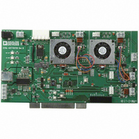
BOARD EVALUATION FOR ADT7467
Manufacturer
Analog Devices Inc
Series
dBCool®r
Datasheet
1.EVAL-ADT7467EB.pdf
(80 pages)
Specifications of EVAL-ADT7467EB
Sensor Type
Temperature
Sensing Range
-40°C ~ 120°C
Interface
SMBus (2-Wire/I²C)
Sensitivity
±1.5°C
Voltage - Supply
3 V ~ 5.5 V
Embedded
No
Utilized Ic / Part
ADT7467
Lead Free Status / RoHS Status
Contains lead / RoHS non-compliant


ADT7467
Because the MOSFET can handle up to 3.5 A, it is simply a
matter of connecting another fan directly in parallel with the
first. Care should be taken in designing drive circuits with
transistors and FETs to ensure that the PWM pins are not
required to source current and that they sink less than the
5 mA maximum current specified on the data sheet.
Driving up to Three Fans from PWM3
TACH measurements for fans are synchronized to particular
PWM channels; for example, TACH1 is synchronized to
PWM1. TACH3 and TACH4 are both synchronized to PWM3;
therefore, PWM3 can drive two fans. Alternatively, PWM3 can
be programmed to synchronize TACH2, TACH3, and TACH4
to the PWM3 output. This allows PWM3 to drive two or three
fans. In this case, the drive circuitry is as shown in Figure 37
and Figure 38. The SYNC bit in Register 0x62 enables this
function.
Synchronization is not required in high frequency mode when
used with 4-wire fans.
<4> (SYNC) Enhance Acoustics Register 1 (Reg. 0x62)
SYNC = 1 synchronizes TACH2, TACH3, and TACH4 to
PWM3.
Figure 38. Interfacing Two Fans in Parallel to the PWM3 Output Using a Single N-Channel MOSFET
Figure 37. Interfacing Two Fans in Parallel to the PWM3 Output Using Low Cost NPN Transistors
ADT7467
ADT7467
TACH4
TACH3
PWM3
PWM3
3.3V
3.3V
3.3V
3.3V
1kΩ
10kΩ
TYPICAL
10kΩ
TYPICAL
10kΩ
TYPICAL
2.2kΩ
TACH
Rev. A | Page 28 of 80
3.3V
+V
TACH3
Q1
MMBT3904
Q1
NDT3055L
10Ω
10Ω
5V OR
12V FAN
Driving 2-Wire Fans
The ADT7467 can only support 2-wire fans when low frequency
PWM mode is selected in Configuration Register 5, Bit 2. If this
bit is not set to 1, the ADT7467 cannot measure the speed of
2-wire fans.
Figure 39 shows how a 2-wire fan can be connected to the
ADT7467. This circuit allows the speed of a 2-wire fan to be
measured, even though the fan has no dedicated TACH signal.
A series resistor, R
commutation pulses into a voltage, which is ac-coupled into the
ADT7467 through the 0.01 μF capacitor. On-chip signal
conditioning allows accurate monitoring of fan speed. The
value of R
the current drawn by the fan. For fans drawing approximately
200 mA, a 2 Ω R
programmed as 40 mV.
For fans that draw more current, such as larger desktop or
server fans, R
threshold. The smaller the threshold programmed, the better,
because more voltage is developed across the fan and the fan
spins faster. Figure 40 shows a typical plot of the sensing
waveform at the TACH/AIN pin.
Q2
MMBT2222
MMBT2222
1N4148
TACH
Q3
SENSE
SENSE
+V
12V
depends on the programmed input threshold and
SENSE
can be reduced for the same programmed
SENSE
5V OR
12V FAN
TACH4
value is suitable when the threshold is
, in the fan circuit converts the fan
Related parts for EVAL-ADT7467EB
Image
Part Number
Description
Manufacturer
Datasheet
Request
R


Part Number:
Description:
BOARD EVAL FOR SI270X-A
Manufacturer:
Silicon Laboratories Inc
Datasheet:

Part Number:
Description:
BUCK CONV REF DESIGN KIT IP1201
Manufacturer:
International Rectifier
Datasheet:
Part Number:
Description:
BOARD DEMO SYNC DUAL BUCK CNVTER
Manufacturer:
International Rectifier
Datasheet:
Part Number:
Description:
BOARD DEMO SYNC BUCK CONVETER
Manufacturer:
International Rectifier
Datasheet:

Part Number:
Description:
EVALBOARD/EB Omnidirectional microphone - Analog
Manufacturer:
Analog Devices
Datasheet:
Part Number:
Description:
EVALBOARD/EB Omnidirectional microphone - Analog
Manufacturer:
Analog Devices
Datasheet:


Part Number:
Description:
BOARD EVAL LED DRIVER LT3756
Manufacturer:
Linear Technology
Datasheet:

Part Number:
Description:
BOARD EVAL FOR AD7741/7742
Manufacturer:
Analog Devices Inc
Datasheet:

Part Number:
Description:
±1.7g Dual-Axis IMEMS Accelerometer Evaluation Board
Manufacturer:
Analog Devices Inc
Datasheet:

Part Number:
Description:
IC MULTIPLIER ANALOG 8-SOIC T/R
Manufacturer:
Analog Devices Inc
Datasheet:

Part Number:
Description:
IC ANALOG MULTIPLIER 8-DIP
Manufacturer:
Analog Devices Inc
Datasheet:
Part Number:
Description:
IC ANALOG MULTIPLIER 8-SOIC
Manufacturer:
Analog Devices Inc
Datasheet:
Part Number:
Description:
IC ANALOG MULTIPLIER 8-DIP
Manufacturer:
Analog Devices Inc
Datasheet: