PIC16F690DM-PCTLHS Microchip Technology, PIC16F690DM-PCTLHS Datasheet - Page 83
PIC16F690DM-PCTLHS
Manufacturer Part Number
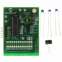
PIC16F690DM-PCTLHS
Description
BOARD DEMO PICTAIL HUMIDITY SNSR
Manufacturer
Microchip Technology
Series
PICtail™r
Datasheets
1.PIC16F690DM-PCTLHS.pdf
(36 pages)
2.PIC16F690DM-PCTLHS.pdf
(32 pages)
3.PIC16F690DM-PCTLHS.pdf
(306 pages)
4.PIC16F690DM-PCTLHS.pdf
(14 pages)
Specifications of PIC16F690DM-PCTLHS
Sensor Type
Humidity
Sensing Range
1 ~ 99% RH
Interface
Analog
Voltage - Supply
5V
Embedded
Yes, MCU, 8-Bit
Utilized Ic / Part
MCP6291, PIC16F690
Processor To Be Evaluated
MCP6291 and PIC16F690
Interface Type
ICSP
Lead Free Status / RoHS Status
Lead free / RoHS Compliant
For Use With
AC162061 - HEADER INTRFC MPLAB ICD2 20PIN
Sensitivity
-
Lead Free Status / RoHS Status
Lead free / RoHS Compliant, Lead free / RoHS Compliant


5.0
The Timer0 module is an 8-bit timer/counter with the
following features:
• 8-bit timer/counter register (TMR0)
• 8-bit prescaler (shared with Watchdog Timer)
• Programmable internal or external clock source
• Programmable external clock edge selection
• Interrupt on overflow
Figure 5-1 is a block diagram of the Timer0 module.
FIGURE 5-1:
© 2008 Microchip Technology Inc.
T0CKI
SWDTEN
pin
Note 1:
WDTE
F
INTOSC
TIMER0 MODULE
OSC
31 kHz
T0SE
2:
3:
/4
T0SE, T0CS, PSA, PS<2:0> are bits in the OPTION register.
SWDTEN and WDTPS<3:0> are bits in the WDTCON register.
WDTE bit is in the Configuration Word register.
BLOCK DIAGRAM OF THE TIMER0/WDT PRESCALER
Watchdog
Timer
T0CS
0
1
PIC16F631/677/685/687/689/690
PSA
Prescaler
0
1
16-bit
16
Prescaler
WDTPS<3:0>
8-bit
8
PS<2:0>
5.1
When used as a timer, the Timer0 module can be used
as either an 8-bit timer or an 8-bit counter.
5.1.1
When used as a timer, the Timer0 module will
increment every instruction cycle (without prescaler).
Timer mode is selected by clearing the T0CS bit of the
OPTION register to ‘0’.
When TMR0 is written, the increment is inhibited for
two instruction cycles immediately following the write.
5.1.2
When used as a counter, the Timer0 module will
increment on every rising or falling edge of the T0CKI
pin. The incrementing edge is determined by the T0SE
bit of the OPTION register. Counter mode is selected by
setting the T0CS bit of the OPTION register to ‘1’.
Note:
Timer0 Operation
8-BIT TIMER MODE
The value written to the TMR0 register can
be adjusted, in order to account for the two
instruction cycle delay when TMR0 is
written.
8-BIT COUNTER MODE
PSA
PSA
1
0
1
0
Sync 2
Time-out
cycles
WDT
DS41262E-page 81
Data Bus
Set Flag bit T0IF
8
TMR0
on Overflow
Related parts for PIC16F690DM-PCTLHS
Image
Part Number
Description
Manufacturer
Datasheet
Request
R

Part Number:
Description:
Manufacturer:
Microchip Technology Inc.
Datasheet:
Part Number:
Description:
Manufacturer:
Microchip Technology Inc.
Datasheet:
Part Number:
Description:
Manufacturer:
Microchip Technology Inc.
Datasheet:
Part Number:
Description:
Manufacturer:
Microchip Technology Inc.
Datasheet:
Part Number:
Description:
Manufacturer:
Microchip Technology Inc.
Datasheet:
Part Number:
Description:
Manufacturer:
Microchip Technology Inc.
Datasheet:
Part Number:
Description:
Manufacturer:
Microchip Technology Inc.
Datasheet:
Part Number:
Description:
Manufacturer:
Microchip Technology Inc.
Datasheet: