STEVAL-MKI024V1 STMicroelectronics, STEVAL-MKI024V1 Datasheet - Page 15
STEVAL-MKI024V1
Manufacturer Part Number
STEVAL-MKI024V1
Description
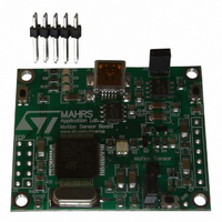
DEMO BOARD BASED ON LIS331DL
Manufacturer
STMicroelectronics
Series
MEMSr
Datasheets
1.STEVAL-MKI024V1.pdf
(42 pages)
2.STEVAL-MKI024V1.pdf
(39 pages)
3.STEVAL-MKI024V1.pdf
(4 pages)
Specifications of STEVAL-MKI024V1
Design Resources
STEVAL-MKI024V1 Gerber Files STEVAL-MKI024V1 Schematics STEVAL-MKI024V1 Bill of Materials
Sensor Type
Accelerometer, 3 Axis
Sensing Range
±2.3g, 9.2g
Interface
SPI, USB
Sensitivity
72mg/digit
Voltage - Supply
5V, USB
Embedded
Yes, MCU, 8-Bit
Utilized Ic / Part
LIS331DL
Acceleration
2 g, 8 g
Sensing Axis
Triple Axis
Output Type
Digital
Interface Type
USB
Silicon Manufacturer
ST Micro
Silicon Core Number
LIS331DL
Kit Application Type
Sensing - Motion / Vibration / Shock
Application Sub Type
Accelerometer
Kit Contents
Board
Lead Free Status / RoHS Status
Lead free / RoHS Compliant
Other names
497-8719
Available stocks
Company
Part Number
Manufacturer
Quantity
Price
Company:

Part Number:
STEVAL-MKI024V1
Manufacturer:
STMicroelectronics
Quantity:
135


LIS331DL
2.5
2.5.1
2.5.2
2.5.3
2.5.4
Terminology
Sensitivity
Sensitivity describes the gain of the sensor and can be determined e.g. by applying 1 g
acceleration to it. As the sensor can measure DC accelerations this can be done easily by
pointing the axis of interest towards the center of the Earth, noting the output value, rotating
the sensor by 180 degrees (pointing to the sky) and noting the output value again. By doing
so, ±1 g acceleration is applied to the sensor. Subtracting the larger output value from the
smaller one, and dividing the result by 2, leads to the actual sensitivity of the sensor. This
value changes very little over temperature and also over time. The Sensitivity Tolerance
describes the range of sensitivities of a large population of sensors.
Zero-g level
Zero-g level Offset (TyOff) describes the deviation of an actual output signal from the ideal
output signal if no acceleration is present. A sensor in a steady state on a horizontal surface
will measure 0 g in X axis and 0 g in Y axis whereas the Z axis will measure 1 g. The output
is ideally in the middle of the dynamic range of the sensor (content of OUT registers 00h,
data expressed as 2’s complement number). A deviation from ideal value in this case is
called Zero-g offset. Offset is to some extent a result of stress to MEMS sensor and
therefore the offset can slightly change after mounting the sensor onto a printed circuit
board or exposing it to extensive mechanical stress. Offset changes little over temperature,
see “Zero-g level change vs. temperature”. The Zero-g level tolerance (TyOff) describes the
Standard Deviation of the range of Zero-g levels of a population of sensors.
Self test
Self Test allows to check the sensor functionality without moving it. The self test function is
off when the self-test bit of CTRL_REG1 (control register 1) is programmed to ‘0‘. When the
self-test bit of ctrl_reg1 is programmed to ‘1‘ an actuation force is applied to the sensor,
simulating a definite input acceleration. In this case the sensor outputs will exhibit a change
in their DC levels which are related to the selected full scale through the device sensitivity.
When Self Test is activated, the device output level is given by the algebraic sum of the
signals produced by the acceleration acting on the sensor and by the electrostatic test-force.
If the output signals change within the amplitude specified inside
working properly and the parameters of the interface chip are within the defined
specifications.
Click and double click recognition
The click and double click recognition functions help to create man-machine interface with
little software overload. The device can be configured to output an interrupt signal on
dedicated pin when tapped in any direction.
If the sensor is exposed to a single input stimulus it generates an interrupt request on inertial
interrupt pins (INT1 and/or INT2). A more advanced feature allows to generate an interrupt
request when a “double click” stimulus is applied. A programmable time between the two
events allows a flexible adaption to the application requirements. Mouse-button like
application, like clicks and double clicks, can be implemented.
This function can be fully programmed by the user in terms of expected amplitude and
timing of the stimuli.
Mechanical and electrical specifications
Table
3, then the sensor is
15/42
Related parts for STEVAL-MKI024V1
Image
Part Number
Description
Manufacturer
Datasheet
Request
R

Part Number:
Description:
BOARD EVAL FOR MEMS SENSORS
Manufacturer:
STMicroelectronics
Datasheet:

Part Number:
Description:
EVALBOARD/STEVAL-ISV014V1
Manufacturer:
STMicroelectronics
Part Number:
Description:
BOARD EVAL FOR ST802RT1
Manufacturer:
STMicroelectronics
Datasheet:

Part Number:
Description:
BOARD EVAL FOR VACUUM CLEANER
Manufacturer:
STMicroelectronics
Datasheet:

Part Number:
Description:
KIT DEV STARTER ST10F276Z5
Manufacturer:
STMicroelectronics
Datasheet:

Part Number:
Description:
BOARD LED CTLR/DVR STLED316S
Manufacturer:
STMicroelectronics
Datasheet:

Part Number:
Description:
BOARD EVAL BLDC SENSORLESS MOTOR
Manufacturer:
STMicroelectronics
Datasheet:

Part Number:
Description:
BOARD ELECT FISCAL CASH REGISTER
Manufacturer:
STMicroelectronics
Datasheet:

Part Number:
Description:
BOARD EVAL BIPO SOLUTION FOR PFC
Manufacturer:
STMicroelectronics
Datasheet:

Part Number:
Description:
BOARD EVAL UPS 450W VOUT=220V
Manufacturer:
STMicroelectronics
Datasheet:
Part Number:
Description:
STMicroelectronics [RIPPLE-CARRY BINARY COUNTER/DIVIDERS]
Manufacturer:
STMicroelectronics
Datasheet:
Part Number:
Description:
STMicroelectronics [LIQUID-CRYSTAL DISPLAY DRIVERS]
Manufacturer:
STMicroelectronics
Datasheet:
Part Number:
Description:
BOARD EVAL FOR MEMS SENSORS
Manufacturer:
STMicroelectronics
Datasheet: