EVAL-AD7147EBZ Analog Devices Inc, EVAL-AD7147EBZ Datasheet - Page 30
EVAL-AD7147EBZ
Manufacturer Part Number
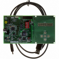
EVAL-AD7147EBZ
Description
BOARD EVAL FOR AD7147ACPZ
Manufacturer
Analog Devices Inc
Series
CapTouch™r
Specifications of EVAL-AD7147EBZ
Sensor Type
Touch, Capacitive
Interface
SPI Serial
Voltage - Supply
2.6 V ~ 3.6 V
Embedded
Yes, MCU, 8-Bit
Utilized Ic / Part
AD7147
Silicon Manufacturer
Analog Devices
Application Sub Type
CapTouch Controller
Kit Application Type
Data Converter
Silicon Core Number
AD7147
Kit Contents
CapTouch Evaluation Board, USB Cable
Rohs Compliant
Yes
Lead Free Status / RoHS Status
Lead free / RoHS Compliant
Sensitivity
-
Sensing Range
-
Lead Free Status / Rohs Status
Compliant


AD7147
GPIO INT OUTPUT CONTROL
The INT output signal can be controlled by the GPIO pin when
the GPIO is configured as an input. The GPIO is con-figured as
an input by setting the GPIO_SETUP bits in the interrupt con-
figuration register to 01. See the
(GPIO)
Enable the GPIO interrupt by setting the GPIO_INT_ENABLE
bit in Register 0x007 to 1, or disable the GPIO interrupt by
clearing this bit to 0. The GPIO status bit in the conversion-
complete interrupt status register reflects the status of the GPIO
GPIO INPUT HIGH WHEN REGISTER IS READ BACK
GPIO INPUT LOW WHEN REGISTER IS READ BACK
READBACK
1
OUTPUT
OUTPUT
READ GPIO_INT_STATUS BIT TO RESET INT OUTPUT.
SERIAL
INPUT
INPUT
Figure 43. Example of INT Output Controlled by the GPIO Input
GPIO
GPIO
INT
INT
section for more information on configuring the GPIO.
(GP IO_SETUP = 01, GPIO_INPUT_CONFIG = 00)
General-Purpose Input/Output
1
Rev. B | Page 30 of 72
interrupt. This bit is set to 1 when the GPIO has triggered INT .
The bit is cleared upon reading the GPIO_INT_STATUS bit if the
condition that caused the interrupt is no longer present.
The GPIO interrupt can be set to trigger on a rising edge, falling
edge, high level, or low level at the GPIO input pin. Table 15 shows
how the settings of the GPIO_INPUT_CONFIG bits in the inter-
rupt enable (STAGE_LOW_INT_ENABLE) register affect the
behavior of INT .
Figure 43 to Figure 46 show how the interrupt output is cleared
upon a read from the GPIO_INT_STATUS bit.
GPIO INPUT HIGH WHEN REGISTER IS READ BACK
GPIO INPUT LOW WHEN REGISTER IS READ BACK
READBACK
1
OUTPUT
OUTPUT
READ GPIO_INT_STATUS BIT TO RESET INT OUTPUT.
SERIAL
INPUT
INPUT
Figure 44. Example of INT Output Controlled by the GPIO Input
GPIO
GPIO
INT
INT
(GPIO_SETUP = 01, GPIO_INPUT_CONFIG = 01)
1
Related parts for EVAL-AD7147EBZ
Image
Part Number
Description
Manufacturer
Datasheet
Request
R


Part Number:
Description:
BOARD EVAL FOR SI270X-A
Manufacturer:
Silicon Laboratories Inc
Datasheet:

Part Number:
Description:
BUCK CONV REF DESIGN KIT IP1201
Manufacturer:
International Rectifier
Datasheet:
Part Number:
Description:
BOARD DEMO SYNC DUAL BUCK CNVTER
Manufacturer:
International Rectifier
Datasheet:
Part Number:
Description:
BOARD DEMO SYNC BUCK CONVETER
Manufacturer:
International Rectifier
Datasheet:

Part Number:
Description:
EVALBOARD/EB Omnidirectional microphone - Analog
Manufacturer:
Analog Devices
Datasheet:
Part Number:
Description:
EVALBOARD/EB Omnidirectional microphone - Analog
Manufacturer:
Analog Devices
Datasheet:


Part Number:
Description:
BOARD EVAL LED DRIVER LT3756
Manufacturer:
Linear Technology
Datasheet:

Part Number:
Description:
BOARD EVAL FOR AD7741/7742
Manufacturer:
Analog Devices Inc
Datasheet:

Part Number:
Description:
±1.7g Dual-Axis IMEMS Accelerometer Evaluation Board
Manufacturer:
Analog Devices Inc
Datasheet:

Part Number:
Description:
IC MULTIPLIER ANALOG 8-SOIC T/R
Manufacturer:
Analog Devices Inc
Datasheet:

Part Number:
Description:
IC ANALOG MULTIPLIER 8-DIP
Manufacturer:
Analog Devices Inc
Datasheet:
Part Number:
Description:
IC ANALOG MULTIPLIER 8-SOIC
Manufacturer:
Analog Devices Inc
Datasheet:
Part Number:
Description:
IC ANALOG MULTIPLIER 8-DIP
Manufacturer:
Analog Devices Inc
Datasheet: