EVAL-AD7147EBZ Analog Devices Inc, EVAL-AD7147EBZ Datasheet - Page 2
EVAL-AD7147EBZ
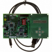
Manufacturer Part Number
EVAL-AD7147EBZ
Description
BOARD EVAL FOR AD7147ACPZ
Manufacturer
Analog Devices Inc
Series
CapTouch™r
Specifications of EVAL-AD7147EBZ
Sensor Type
Touch, Capacitive
Interface
SPI Serial
Voltage - Supply
2.6 V ~ 3.6 V
Embedded
Yes, MCU, 8-Bit
Utilized Ic / Part
AD7147
Silicon Manufacturer
Analog Devices
Application Sub Type
CapTouch Controller
Kit Application Type
Data Converter
Silicon Core Number
AD7147
Kit Contents
CapTouch Evaluation Board, USB Cable
Rohs Compliant
Yes
Lead Free Status / RoHS Status
Lead free / RoHS Compliant
Sensitivity
-
Sensing Range
-
Lead Free Status / Rohs Status
Compliant


AD7147
TABLE OF CONTENTS
Features .............................................................................................. 1
Applications ....................................................................................... 1
General Description ......................................................................... 1
Functional Block Diagram .............................................................. 1
Revision History ............................................................................... 2
Specifications ..................................................................................... 3
Absolute Maximum Ratings ............................................................ 7
Pin Configurations and Function Descriptions ........................... 8
Typical Performance Characteristics ............................................. 9
Theory of Operation ...................................................................... 11
Capacitiance-to-Digital Converter ............................................... 14
Capacitance Sensor Input Configuration .................................... 17
Noncontact Proximity Detection ................................................. 18
Environmental Calibration ........................................................... 23
REVISION HISTORY
7/09—Rev. A to Rev. B
Changes to BIAS Pin Description .................................................. 8
Changes to BIAS Pin Section ........................................................ 12
8/08—Rev. 0 to Rev. A
Changes to Table 3 ............................................................................ 4
Added Figure 3, Renumbered Sequentially .................................. 6
Changes to Low Power Mode Section ......................................... 13
Average Current Specifications .................................................. 4
SPI Timing Specifications (AD7147) ......................................... 5
I
ESD Caution .................................................................................. 7
Capacitance Sensing Theory ..................................................... 11
BIAS Pin ....................................................................................... 12
Operating Modes ........................................................................ 12
Oversampling the CDC Output ............................................... 14
Capacitance Sensor Offset Control .......................................... 14
Conversion Sequencer ............................................................... 14
CDC Conversion Sequence Time ............................................ 16
CDC Conversion Results ........................................................... 16
CINx Input Multiplexer Setup .................................................. 17
Single-Ended Connections to the CDC .................................. 17
Recalibration ............................................................................... 18
Proximity Sensitivity .................................................................. 18
FF_SKIP_CNT ............................................................................ 21
2
C Timing Specifications (AD7147-1) ..................................... 6
Rev. B | Page 2 of 72
Adaptive Threshold and Sensitivity ............................................. 26
Interrupt Output ............................................................................. 28
Outputs ............................................................................................ 32
Serial Interface ................................................................................ 33
PCB Design Guidelines ................................................................. 38
Power-Up Sequence ....................................................................... 39
Typical Application Circuits ......................................................... 40
Register Map ................................................................................... 41
Detailed Register Descriptions ..................................................... 42
Outline Dimensions ....................................................................... 69
Added Latency from Touch to Response Section ...................... 13
Added Low Latency from Touch to Response Section .............. 13
Changes to Figure 60 and Figure 61............................................. 40
Changes to Figure 62 ...................................................................... 41
Added Exposed Pad Notation to Outline Dimensions ............. 68
9/07—Revision 0: Initial Version
Capacitance Sensor Behavior Without Calibration ............... 23
Threshold Equations .................................................................. 24
Capacitance Sensor Behavior with Calibration ...................... 24
Slow FIFO .................................................................................... 24
SLOW_FILTER_UPDATE_LVL .............................................. 25
CDC Conversion-Complete Interrupt .................................... 28
Sensor-Touch Interrupt ............................................................. 28
GPIO INT Output Control ....................................................... 30
AC
General-Purpose Input/Output (GPIO) ................................. 32
Using the GPIO to Turn On/Off an LED ................................ 32
SPI Interface ................................................................................ 33
I
V
Capacitive Sensor Board Mechanical Specifications ............. 38
Chip Scale Packages ................................................................... 38
Bank 1 Registers ......................................................................... 42
Bank 2 Registers ......................................................................... 52
Bank 3 Registers ......................................................................... 57
Ordering Guide .......................................................................... 69
2
C-Compatible Interface .......................................................... 35
DRIVE
SHIELD
Input ................................................................................. 37
Output .......................................................................... 32
Related parts for EVAL-AD7147EBZ
Image
Part Number
Description
Manufacturer
Datasheet
Request
R


Part Number:
Description:
BOARD EVAL FOR SI270X-A
Manufacturer:
Silicon Laboratories Inc
Datasheet:

Part Number:
Description:
BUCK CONV REF DESIGN KIT IP1201
Manufacturer:
International Rectifier
Datasheet:
Part Number:
Description:
BOARD DEMO SYNC DUAL BUCK CNVTER
Manufacturer:
International Rectifier
Datasheet:
Part Number:
Description:
BOARD DEMO SYNC BUCK CONVETER
Manufacturer:
International Rectifier
Datasheet:

Part Number:
Description:
EVALBOARD/EB Omnidirectional microphone - Analog
Manufacturer:
Analog Devices
Datasheet:
Part Number:
Description:
EVALBOARD/EB Omnidirectional microphone - Analog
Manufacturer:
Analog Devices
Datasheet:


Part Number:
Description:
BOARD EVAL LED DRIVER LT3756
Manufacturer:
Linear Technology
Datasheet:

Part Number:
Description:
BOARD EVAL FOR AD7741/7742
Manufacturer:
Analog Devices Inc
Datasheet:

Part Number:
Description:
±1.7g Dual-Axis IMEMS Accelerometer Evaluation Board
Manufacturer:
Analog Devices Inc
Datasheet:

Part Number:
Description:
IC MULTIPLIER ANALOG 8-SOIC T/R
Manufacturer:
Analog Devices Inc
Datasheet:

Part Number:
Description:
IC ANALOG MULTIPLIER 8-DIP
Manufacturer:
Analog Devices Inc
Datasheet:
Part Number:
Description:
IC ANALOG MULTIPLIER 8-SOIC
Manufacturer:
Analog Devices Inc
Datasheet:
Part Number:
Description:
IC ANALOG MULTIPLIER 8-DIP
Manufacturer:
Analog Devices Inc
Datasheet: