STEVAL-ISA056V1 STMicroelectronics, STEVAL-ISA056V1 Datasheet - Page 30
STEVAL-ISA056V1
Manufacturer Part Number
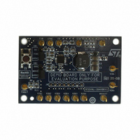
STEVAL-ISA056V1
Description
BOARD EVAL BASED ON PM6600
Manufacturer
STMicroelectronics
Type
PWM Controllersr
Specifications of STEVAL-ISA056V1
Design Resources
STEVAL-ISA056V1 Gerber Files STEVAL-ISA056V1 Schematic STEVAL-ISA056V1 Bill of Material
Current - Output / Channel
30mA
Outputs And Type
6, Non-Isolated
Voltage - Output
36 V
Features
Dimmable
Voltage - Input
4.5 ~ 28V
Utilized Ic / Part
PM6600
Input Voltage
4.5 V to 28 V
Output Voltage
36 V
Product
Power Management Modules
Core Chip
PM6600
Topology
Boost
No. Of Outputs
1
Dimming Control Type
PWM
Mcu Supported Families
PM6600
Lead Free Status / RoHS Status
Lead free / RoHS Compliant
For Use With/related Products
PM6600
Other names
497-8414
Available stocks
Company
Part Number
Manufacturer
Quantity
Price
Company:

Part Number:
STEVAL-ISA056V1
Manufacturer:
STMicroelectronics
Quantity:
1


Operation description
7.4
7.4.1
30/60
System stability
The boost section of the PM6600 is a fixed frequency, peak current-mode converter. During
normal operation, a minimum voltage selection circuit compares all the voltage drops across
the active current generators and provides the minimum one to the error amplifier. The
output voltage of the error amplifier determines the inductor peak current in order to keep its
inverting input equal to the reference voltage (400 mV typ). The compensation network
consists of a simple RC series (R
The calculation of R
dynamic performance of the boost converter and is strictly related to the operating
conditions.
Loop compensation
The compensation network can be quickly calculated using equations 4 through 9. Once
both R
order to get the optimal dynamic performance from the application.
The first parameter to be fixed is the switching frequency. Normally, a high switching
frequency allows reducing the size of the inductor but increases the switching losses and
negatively affects the dynamic response of the converter. For most of applications, the fixed
value (660 kHz) represents a good trade-off between power dissipation and dynamic
response, allowing to save an external resistor at the same time. In low-profile applications,
the inductor value is often kept low to reduce the number of turns; an inductor value in the
4.7 µH-15 µH range is a good starting choice.
Even if the loop bandwidth of the boost converter should be chosen as large as possible, it
should be set to 20% of the switching frequency, taking care not to exceed the CCM-mode
right half-plane zero (RHPZ).
Equation 7
Equation 8
Where V
Note that, the lower the inductor value (or the lower the switching frequency) the higher the
bandwidth can be achieved. The output capacitor is directly involved in the loop of the boost
converter and must be large enough to avoid excessive output voltage drop in case of a
sudden line transition from the maximum to the minimum input voltages (ΔV
exceed 50-100 mV):
COMP
IN,min
and C
is the minimum input voltage, I
COMP
COMP
have been determined, a fine-tuning phase may be required in
f
and C
U
≤
0
Doc ID 14248 Rev 7
2 .
COMP
M =
COMP
⋅
2
M
⋅ π
V
2
V
R
is fundamental to achieve optimal loop stability and
IN
L
OUT
- C
f
,
U
min
=
≤
COMP
0
0
2 .
2 .
R =
OUT
⋅
⋅
⎛
⎜ ⎜
⎝
) between the COMP pin and ground.
f
SW
V
V
V
IN
I
is the overall output current,
OUT
OUT
OUT
,
min
2
⋅ π
⎞
⎟ ⎟
⎠
2
⎛
⎜ ⎜
⎝
L
V
I
OUT
OUT
⎞
⎟ ⎟
⎠
OUT
should not
PM6600
Related parts for STEVAL-ISA056V1
Image
Part Number
Description
Manufacturer
Datasheet
Request
R

Part Number:
Description:
BOARD RGB CTR ST7,STP08C596MTR
Manufacturer:
STMicroelectronics
Datasheet:

Part Number:
Description:
Power Management IC Development Tools Full Speed USB to RS232 Bridge Demo
Manufacturer:
STMicroelectronics
Datasheet:
Part Number:
Description:
Power Management IC Development Tools 2.5W solar eval BRD USB SPV1040 LD39050
Manufacturer:
STMicroelectronics
Datasheet:

Part Number:
Description:
BOARD EVAL FOR MEMS SENSORS
Manufacturer:
STMicroelectronics
Datasheet:

Part Number:
Description:
KIT DEV STARTER ST10F276Z5
Manufacturer:
STMicroelectronics
Datasheet:

Part Number:
Description:
BOARD EVAL HDMI $ VIDEO SWITCH
Manufacturer:
STMicroelectronics
Datasheet:

Part Number:
Description:
BOARD DEMO ACCELEROMETER DIL24
Manufacturer:
STMicroelectronics
Datasheet:

Part Number:
Description:
BOARD STLM75/STDS75/ST72F651
Manufacturer:
STMicroelectronics
Datasheet:

Part Number:
Description:
EVAL BOARD 3AXIS MEMS ACCELLRMTR
Manufacturer:
STMicroelectronics
Datasheet:

Part Number:
Description:
BOARD EVAL 8BIT MICRO + TDE1708
Manufacturer:
STMicroelectronics
Datasheet:
Part Number:
Description:
STMicroelectronics [RIPPLE-CARRY BINARY COUNTER/DIVIDERS]
Manufacturer:
STMicroelectronics
Datasheet:
Part Number:
Description:
STMicroelectronics [LIQUID-CRYSTAL DISPLAY DRIVERS]
Manufacturer:
STMicroelectronics
Datasheet:
Part Number:
Description:
BOARD EVAL FOR MEMS SENSORS
Manufacturer:
STMicroelectronics
Datasheet: