STEVAL-ILL024V1 STMicroelectronics, STEVAL-ILL024V1 Datasheet - Page 8
STEVAL-ILL024V1
Manufacturer Part Number
STEVAL-ILL024V1
Description
LED BOARD FOR STM32 STP16DP05
Manufacturer
STMicroelectronics
Specifications of STEVAL-ILL024V1
Design Resources
STEVAL-ILL024V1 BOM STEVAL-ILL024V1 Schematic
Current - Output / Channel
100mA
Outputs And Type
16, Non-Isolated
Voltage - Output
20V
Features
Short-Circuit Protection
Voltage - Input
3 ~ 5.5V
Utilized Ic / Part
STM32F103VB, STP16DP05
Description/function
LED Display Demo System Control Unit
Product
Display Modules
For Use With
497-9087 - LED MATRIX DISPLAY PANEL
Lead Free Status / RoHS Status
Lead free / RoHS Compliant
For Use With/related Products
STM32F103VB
Other names
497-9091


System description
2.1.2
2.2
8/30
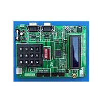
Figure 5.
Selecting the control unit as master or slave
Any control unit can act as the master or slave. The on-board keypad is used to configure
the control unit as master or as slave.
The steps for configuring the control unit are listed below:
Description of the STEVAL-ILL025V1 LED driver-based
display unit
The STEVAL-ILL025V1 display unit is an STP16DP05 LED display driver-based panel.
Each display panel has four STP16DP05 LED display drivers, two buffers, eight Darlington
pairs and a matrix of 16 x 32 LEDs. Each panel can be connected in series to create a larger
display. Series connection between the display panels is done through a 10 x 2 header. A
20-pin flat-ribbon cable is used to connect the two display panels. Input to the display panel
comes from the control unit through the 20-pin flat-ribbon cable. Therefore, the first display
–
–
–
–
–
–
–
Connect a 5 V power supply to the control unit, as explained in
The LCD shows “Press “#” to enter Configuration Mod”, for 4 seconds
Press “#” on the keypad present on the board. The LCD shows “Master Sel: Entr
*1” and “Slave Sel: Entr *2”
To configure the board as the master, press “*1” or to configure the board as the
slave press “*2” on the keypad
If “*1” is pressed, then the LCD shows “Master Board” for 2 seconds and then
starts the master routine on the board
If “*2” is pressed, then the LCD shows “Slave Board” for 2 seconds and then starts
the slave routine on the board.
On the next power-up of the board the message “Press “#” to enter Configuration
Mod” is again shown on the LCD for 4 seconds, but if “#” is not pressed within 4
seconds, the board enters into the last configured mode.
Slave unit address configuration switches
Doc ID 16147 Rev 1
Section 1.3
UM0767
Related parts for STEVAL-ILL024V1
Image
Part Number
Description
Manufacturer
Datasheet
Request
R

Part Number:
Description:
BOARD EVAL FOR MEMS SENSORS
Manufacturer:
STMicroelectronics
Datasheet:

Part Number:
Description:
KIT DEV STARTER ST10F276Z5
Manufacturer:
STMicroelectronics
Datasheet:

Part Number:
Description:
BOARD EVAL HDMI $ VIDEO SWITCH
Manufacturer:
STMicroelectronics
Datasheet:

Part Number:
Description:
BOARD DEMO ACCELEROMETER DIL24
Manufacturer:
STMicroelectronics
Datasheet:

Part Number:
Description:
BOARD STLM75/STDS75/ST72F651
Manufacturer:
STMicroelectronics
Datasheet:

Part Number:
Description:
EVAL BOARD 3AXIS MEMS ACCELLRMTR
Manufacturer:
STMicroelectronics
Datasheet:

Part Number:
Description:
BOARD EVAL 8BIT MICRO + TDE1708
Manufacturer:
STMicroelectronics
Datasheet:

Part Number:
Description:
EVAL BOARD A/D TS4657
Manufacturer:
STMicroelectronics
Datasheet:

Part Number:
Description:
BOARD ADAPTER 20DIP LIS3LV02DL
Manufacturer:
STMicroelectronics
Datasheet:

Part Number:
Description:
BOARD DEMO STM8S207R6/LIS331DLH
Manufacturer:
STMicroelectronics
Datasheet:

Part Number:
Description:
STMicroelectronics [RIPPLE-CARRY BINARY COUNTER/DIVIDERS]
Manufacturer:
STMicroelectronics
Datasheet:
Part Number:
Description:
STMicroelectronics [LIQUID-CRYSTAL DISPLAY DRIVERS]
Manufacturer:
STMicroelectronics
Datasheet:
Part Number:
Description:
BOARD EVAL FOR MEMS SENSORS
Manufacturer:
STMicroelectronics
Datasheet: