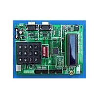
STEVAL-ILL024V1 STMicroelectronics, STEVAL-ILL024V1 Datasheet - Page 18

STEVAL-ILL024V1
Manufacturer Part Number
STEVAL-ILL024V1
Description
LED BOARD FOR STM32 STP16DP05
Manufacturer
STMicroelectronics
Specifications of STEVAL-ILL024V1
Design Resources
STEVAL-ILL024V1 BOM STEVAL-ILL024V1 Schematic
Current - Output / Channel
100mA
Outputs And Type
16, Non-Isolated
Voltage - Output
20V
Features
Short-Circuit Protection
Voltage - Input
3 ~ 5.5V
Utilized Ic / Part
STM32F103VB, STP16DP05
Description/function
LED Display Demo System Control Unit
Product
Display Modules
For Use With
497-9087 - LED MATRIX DISPLAY PANEL
Lead Free Status / RoHS Status
Lead free / RoHS Compliant
For Use With/related Products
STM32F103VB
Other names
497-9091
System operation modes
4.2
Note:
4.3
18/30
GPS communication mode
Global positioning system (GPS) mode is used for interacting with an externally connected
GPS module and display time, latitude, longitude and satellite fixture status.
The steps for communicating with a GPS module are listed below:
Steps:
●
●
●
●
●
●
●
●
●
The GPS module interface is configured for 115200 baud rate.
Key board typing mode
This mode is for user interaction using the keyboard attached at the PS2 connector on the
motherboard.
The steps for operating in typing mode are listed below:
Steps:
●
●
●
●
●
●
Connect a serial cable between the GPS module and the DB9 male connector (VB2) of
the master control unit. The GPS system should follow the handshaking protocol for
serial communication.
Connect the PS2 keyboard to the master control unit.
Power-up the master control unit, the LED panel, and the slave control unit (if
connected).
The master LCD shows the menu program which displays “Press F2 for GPS data
display”.
Press the F2 key on the keyboard attached to the PS2 connector of the master control
unit.
The master LCD shows the GPS mode selected and “Enter Display Board Address”.
Enter the slave board address where data is to be displayed on the LED matrix panel.
Addresses allowed are between 1 and 255. 255 is fixed for the master unit. If the wrong
data is entered the LCD shows “Address Mismatch” and again asks for the address.
When the address is matched, the LCD asks for the number of display panels
connected in cascade at the selected slave device to be entered.
As soon as the number of display panels is entered, the LED matrix starts showing
time, latitude, longitude and satellite fixture status.
Press Esc on the keyboard to exit GPS mode and return to the main menu.
Connect the keyboard to the PS2 connector on the master control unit.
Power-up the master control unit, the LED panel, and the slave control unit (if present).
The master LCD shows the menu program which displays “Press F3 for typing data”.
Press the F3 key on the keyboard attached to the PS2 connector of the master control
unit.
The master LCD shows “Enter Display Board Address”. Enter the slave board address
where data is to be displayed on the LED matrix panel. The addresses allowed are
between 1 and 255. 255 is fixed for the master unit. If the wrong data is entered then
the LCD shows “Address Mismatch”, and again asks for the address.
When the address is matched, the LCD shows “Enter No. Of LED Boards”. Enter the
number of LED panels connected in cascade to the selected control unit (one LED
Doc ID 16147 Rev 1
UM0767


