STEVAL-ILL024V1 STMicroelectronics, STEVAL-ILL024V1 Datasheet - Page 10
STEVAL-ILL024V1
Manufacturer Part Number
STEVAL-ILL024V1
Description
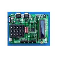
LED BOARD FOR STM32 STP16DP05
Manufacturer
STMicroelectronics
Specifications of STEVAL-ILL024V1
Design Resources
STEVAL-ILL024V1 BOM STEVAL-ILL024V1 Schematic
Current - Output / Channel
100mA
Outputs And Type
16, Non-Isolated
Voltage - Output
20V
Features
Short-Circuit Protection
Voltage - Input
3 ~ 5.5V
Utilized Ic / Part
STM32F103VB, STP16DP05
Description/function
LED Display Demo System Control Unit
Product
Display Modules
For Use With
497-9087 - LED MATRIX DISPLAY PANEL
Lead Free Status / RoHS Status
Lead free / RoHS Compliant
For Use With/related Products
STM32F103VB
Other names
497-9091


System configuration
3
3.1
10/30
System configuration
The whole system can be connected in one of the following configurations:
●
●
●
One control unit and one display unit configuration
In this configuration there is a single control unit and a single display unit. The control unit
acts as the master.
The steps to operate the system in this configuration are listed below:
●
●
If needed, the display panels can be cascaded in series to create a longer display. To
cascade the display panels connect a 20-pin flat-ribbon cable from the J3 jumper (output) of
the first panel to the J1 jumper (input) of the second panel.
for cascading the display panels. Similarly, connect the FRC cable from the J3 jumper
(output) of the second panel to the J1 jumper (input) of the third panel and so on to create a
longer display. Up to 8 such display panels can be cascaded in series.
●
●
●
●
●
●
●
●
●
One control unit and one display unit without a slave unit
Two control units (one acting as a master and the other as a slave) and one display unit
Multiple control units (one acting as a master and the others as slaves) and multiple
display units (each display unit connected to each slave. One display unit can have up
to 8 cascaded panels that may be controlled by a single slave unit.)
Step 1: connect the PS2 keyboard to the control unit.
Step 2: connect the control unit with the display panel using a 20-pin flat-ribbon cable.
Insert the cable into the 10 x 2 header (Ext.Con) present on the master on one side and
in the J1 header (input) on the display panel on the other side.
Step 3: connect the power to the master control unit and to the display panel, as
explained in
Step 4: the LCD on the master control unit shows “Press “#” to enter Configuration
Mod”, for 4 seconds.
Step 5: press “#” on the keypad present on the board. If 4 seconds elapse and the
board is not configured, then it enters into the last configured mode. To configure it
again, press the reset button.
Step 6: if “#” is pressed then the LCD shows “Master Sel: Entr *1” and “Slave Sel: Entr
*2”.
Step 7: press “*1” on the keypad. The LCD shows “Master Board”.
Step 8: after 2 Seconds the LCD starts the demo showing “Led Matrix Demo”.
Step 9: the display starts showing 4 options:
–
–
–
–
Step 10: press F1, F2, F3 or F6 on the keyboard to select one of the above mentioned
modes.
Step 11: based on which of the keys listed above is pressed, the system enters into the
chosen mode. Operation in each mode is explained in
Press F1 For PC - UART Comm
Press F2 For GPS Data Display
Press F3 For Typing Data
Press F6 For Demo Mode
Section
1.3.
Doc ID 16147 Rev 1
Figure 6
Section
4.
shows the connections
UM0767
Related parts for STEVAL-ILL024V1
Image
Part Number
Description
Manufacturer
Datasheet
Request
R

Part Number:
Description:
BOARD EVAL FOR MEMS SENSORS
Manufacturer:
STMicroelectronics
Datasheet:

Part Number:
Description:
KIT DEV STARTER ST10F276Z5
Manufacturer:
STMicroelectronics
Datasheet:

Part Number:
Description:
BOARD EVAL HDMI $ VIDEO SWITCH
Manufacturer:
STMicroelectronics
Datasheet:

Part Number:
Description:
BOARD DEMO ACCELEROMETER DIL24
Manufacturer:
STMicroelectronics
Datasheet:

Part Number:
Description:
BOARD STLM75/STDS75/ST72F651
Manufacturer:
STMicroelectronics
Datasheet:

Part Number:
Description:
EVAL BOARD 3AXIS MEMS ACCELLRMTR
Manufacturer:
STMicroelectronics
Datasheet:

Part Number:
Description:
BOARD EVAL 8BIT MICRO + TDE1708
Manufacturer:
STMicroelectronics
Datasheet:

Part Number:
Description:
EVAL BOARD A/D TS4657
Manufacturer:
STMicroelectronics
Datasheet:

Part Number:
Description:
BOARD ADAPTER 20DIP LIS3LV02DL
Manufacturer:
STMicroelectronics
Datasheet:

Part Number:
Description:
BOARD DEMO STM8S207R6/LIS331DLH
Manufacturer:
STMicroelectronics
Datasheet:

Part Number:
Description:
STMicroelectronics [RIPPLE-CARRY BINARY COUNTER/DIVIDERS]
Manufacturer:
STMicroelectronics
Datasheet:
Part Number:
Description:
STMicroelectronics [LIQUID-CRYSTAL DISPLAY DRIVERS]
Manufacturer:
STMicroelectronics
Datasheet:
Part Number:
Description:
BOARD EVAL FOR MEMS SENSORS
Manufacturer:
STMicroelectronics
Datasheet: