EVL6566A-75WADP STMicroelectronics, EVL6566A-75WADP Datasheet - Page 34
EVL6566A-75WADP
Manufacturer Part Number
EVL6566A-75WADP
Description
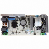
BOARD EVAL FOR L6566A
Manufacturer
STMicroelectronics
Type
Power Factor Correctionr
Datasheets
1.L6566ATR.pdf
(51 pages)
2.TSM1014IDT.pdf
(10 pages)
3.L6563ATR.pdf
(39 pages)
4.EVL6566A-75WADP.pdf
(8 pages)
Specifications of EVL6566A-75WADP
Main Purpose
AC/DC, Primary and Secondary Side with PFC
Outputs And Type
1, Isolated
Power - Output
75W
Voltage - Output
19V
Current - Output
4A
Voltage - Input
90 ~ 264VAC
Frequency - Switching
65kHz
Board Type
Fully Populated
Utilized Ic / Part
L6563, L6566A, TSM1014
Input Voltage
90 V to 264 V
Output Voltage
19 V
Dimensions
78 mm x 174 mm
Product
Power Management Modules
Lead Free Status / RoHS Status
Lead free / RoHS Compliant
Regulator Topology
-
Lead Free Status / Rohs Status
Lead free / RoHS Compliant
For Use With/related Products
L6563, L6566A
Other names
497-6449
Available stocks
Company
Part Number
Manufacturer
Quantity
Price


Application information
Note:
34/51
Figure 21. Soft-start pin operation under different operating conditions and settings
Vcc_PFC
(pin 6)
(pin 14)
(pin 5)
(pin 4)
COMP
(pin 9)
Vcc
GD
SS
2V
5V+2Vbe
START-UP
5V
operating, so that the converter will work intermittently, which is very safe. In case of
overload the system has a power capability lower than that at nominal load but the output
current may be quite high and overstress the output rectifier. In case of FF operation the
capability is almost unchanged and both short circuit and overload conditions are more
critical to handle.
The L6566A, regardless of the operating option selected, makes it easier to handle such
conditions: the 2 V clamp on the SS pin is removed and a second internal current generator
I
is allowed to reach 2 V
resulting behavior will be identical to that under short circuit illustrated in
page 19
See
A diode, with the anode to the SS pin and the cathode connected to the VREF pin (10) is the
simplest way to select either auto-restart mode or latch-mode behavior upon overcurrent. If
the overload disappears before the Css voltage reaches 5 V the I
turned off and the voltage gradually brought back down to 2 V. Refer to the
Application examples and ideas on page 44
hints.
If latch-mode behavior is desired also for converter’s short circuit, make sure that the supply
voltage of the device does not fall below the UVLO threshold before activating the latch.
Figure 21
different settings (latch-mode or autorestart).
Unlike other PWM controllers provided with a soft-start pin, in the L6566A grounding the SS
pin does not guarantee that the gate driver is disabled.
SS2
= I
Section 5.9: Latched disable function on page 32
SS1
OPERATION
; in the latter case the result will be identical to that of
NORMAL
shows soft-start pin behavior under different operating conditions and with
/4 keeps on charging Css. As the voltage reaches 5 V the device is disabled, if it
TEMPORARY
OVERLOAD
BE
over 5 V, the device will be latched off. In the former case the
OPERATION
NORMAL
section (
OVERLOAD
Vcc falls below UVLO
before latching off
here the IC
shuts down
Figure 7 on page 45
for additional details.
Figure 20 on page 33
SS2
SHUTDOWN
generator will be
AUTORESTART
here the IC
latches off
LATCHED
Figure 6 on
) for additional
Section 6:
RESTART
L6566A
.
UVLO
t
t
t
t
t
Related parts for EVL6566A-75WADP
Image
Part Number
Description
Manufacturer
Datasheet
Request
R

Part Number:
Description:
BOARD DEMO FOR L6563/LL6566A
Manufacturer:
STMicroelectronics
Datasheet:

Part Number:
Description:
STMicroelectronics [RIPPLE-CARRY BINARY COUNTER/DIVIDERS]
Manufacturer:
STMicroelectronics
Datasheet:
Part Number:
Description:
STMicroelectronics [LIQUID-CRYSTAL DISPLAY DRIVERS]
Manufacturer:
STMicroelectronics
Datasheet:

Part Number:
Description:
BOARD EVAL FOR MEMS SENSORS
Manufacturer:
STMicroelectronics
Datasheet:
Part Number:
Description:
NPN TRANSISTOR POWER MODULE
Manufacturer:
STMicroelectronics
Datasheet:
Part Number:
Description:
TURBOSWITCH ULTRA-FAST HIGH VOLTAGE DIODE
Manufacturer:
STMicroelectronics
Datasheet:
Part Number:
Description:
Manufacturer:
STMicroelectronics
Datasheet:
Part Number:
Description:
DIODE / SCR MODULE
Manufacturer:
STMicroelectronics
Datasheet:
Part Number:
Description:
DIODE / SCR MODULE
Manufacturer:
STMicroelectronics
Datasheet:
Part Number:
Description:
Search -----> STE16N100
Manufacturer:
STMicroelectronics
Datasheet:
Part Number:
Description:
Search ---> STE53NA50
Manufacturer:
STMicroelectronics
Datasheet:
Part Number:
Description:
NPN Transistor Power Module
Manufacturer:
STMicroelectronics
Datasheet: