STEVAL-CBL006V1 STMicroelectronics, STEVAL-CBL006V1 Datasheet - Page 7
STEVAL-CBL006V1
Manufacturer Part Number
STEVAL-CBL006V1
Description
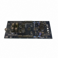
DEMO BOARD BASED ON LNBH24
Manufacturer
STMicroelectronics
Type
DC/DC Switching Converters, Regulators & Controllersr
Specifications of STEVAL-CBL006V1
Main Purpose
Special Purpose DC/DC, LNB
Outputs And Type
2, Non-Isolated
Voltage - Input
8 ~ 15V
Regulator Topology
Boost
Board Type
Fully Populated
Utilized Ic / Part
LNBH24
Input Voltage
12 V
Interface Type
I2C
Product
Power Management Modules
Supply Current
500 mA
Silicon Manufacturer
ST Micro
Silicon Core Number
LNBH24
Kit Application Type
Power Management
Application Sub Type
LNB Power Supply
Kit Contents
Board
Lead Free Status / RoHS Status
Lead free / RoHS Compliant
Current - Output
-
Voltage - Output
-
Power - Output
-
Frequency - Switching
-
Lead Free Status / Rohs Status
Lead free / RoHS Compliant
For Use With/related Products
LNBH24
Other names
497-8718


2.8
2.9
2.10
2.11
The LNBH24 is also compliant with the USA LNB power supply standards. In order to allow
fast transition of the output voltage from 18 V to 13 V and vice-versa, the LNBH24 is
provided with the VCTRL TTL pin which keeps the output at 13 V when it is set LOW and at
18 V when it is set HIGH or floating. VSEL and, if required, LLC bits must be set HIGH
before using the VCTRL pin to switch the output voltage level. If VCTRL = 1 or floating, then
V
Should be noted that the VCTRL pin controls only the linear regulator V
step-up V
VCTRL = 0 (keeping V
20.25 V with VSEL = LLC = 1. This means that VCTRL = 0 must be used only for short
period to avoid the higher power dissipation. In standby condition (EN bit LOW) all the I²C
bits and the TTX pin must be set LOW (if the TTX pin is not used it can be left floating but
the TTX bit must be set LOW during the standby condition).
Diagnostic and protection functions
The LNBH24 has 5 diagnostic internal functions provided via I²C BUS by reading 5 bits on
the system register (SR bits in read mode). All the diagnostic bits are, in normal operation
(no failure detected), set to LOW. Two diagnostic bits are dedicated to the over-temperature
and over-load protection status (OTF and OLF), while the remaining 3 bits are dedicated to
the output voltage level (VMON), 22 kHz Tone (TMON) and to the Minimum Load Current
diagnostic function (IMON).
Output voltage diagnostic
When VSEL = 0 or 1 and LLC = 0, the output voltage pin (V
as long as the output voltage level is below the guaranteed limits, the VMON I²C bit is set to
"1". The output voltage diagnostic is valid only with LLC = 0 and AUX = 0. Any VMON
information with LLC = 1 and/or AUX = 1 must be disregarded by the MCU.
22 kHz tone diagnostic
The 22 kHz tone can be internally detected and monitored If the DETIN pin is connected to
the LNB output bus (see typical application circuits) through a decoupling capacitor. The
Tone diagnostic function is provided with the TMON I²C bit. If the 22 kHz Tone amplitude
and/or the Tone frequency is out of the guaranteed limits (see TMON limits in the electrical
characteristics in
Minimum output current diagnostic
In order to detect the output load absence (no LNB connected on the bus or cable not
connected to the IRD) the LNBH24 is provided with a minimum output current flag by the
IMON I²C bit in read mode, which is set to "1" if the output current is lower than 12 mA
typically with ITEST=1, and 6 mA with ITEST=0. The minimum current diagnostic function
(IMON) is always active. In order for it to function even in a multi-IRD configuration (multi-
switch), where the supply current could be sunk only from the higher supply voltage
connected to the multi-switch box, the LNBH24 is provided with the AUX I²C bit. To force the
LNBH24 output voltage as the highest voltage on the bus (22 V typ.) during the minimum
current diagnostic phase, the AUX I²C bit can be set HIGH before reading the IMON I²C bit
status. When the AUX bit is set to HIGH, the V
OUT
= 18.5 V (or 19.5 V if LLC=1). With VCTRL=0 V
UP
voltage is controlled only through the VSEL and LLC I²C bits. That is, even if
Table
OUT
13), the TMON I²C Bit is set to "1".
= 13.4 V) you will have V
OUT
is set to 22 V (typ.) and the V
UP
OUT
= 19.25 V typ when VSEL = 1 and
=13.4 V (LLC= either 0 or 1).
oRX
) is internally monitored and,
OUT
stage while the
UP
is set to
7/30
Related parts for STEVAL-CBL006V1
Image
Part Number
Description
Manufacturer
Datasheet
Request
R

Part Number:
Description:
BOARD EVAL FOR MEMS SENSORS
Manufacturer:
STMicroelectronics
Datasheet:

Part Number:
Description:
KIT DEV STARTER ST10F276Z5
Manufacturer:
STMicroelectronics
Datasheet:

Part Number:
Description:
BOARD EVAL UPS 450W VOUT=220V
Manufacturer:
STMicroelectronics
Datasheet:

Part Number:
Description:
BOARD STLM75/STDS75/ST72F651
Manufacturer:
STMicroelectronics
Datasheet:

Part Number:
Description:
EVAL BOARD ENERGY METER MONO
Manufacturer:
STMicroelectronics
Datasheet:

Part Number:
Description:
EVAL BOARD ENERGY METER MONO
Manufacturer:
STMicroelectronics
Datasheet:

Part Number:
Description:
EVAL BOARD ENERGY METER MONO
Manufacturer:
STMicroelectronics
Datasheet:

Part Number:
Description:
BOARD EVAL BASED ON TS2012IQT
Manufacturer:
STMicroelectronics
Datasheet:

Part Number:
Description:
BOARD EVAL FOR TS4962MEIJT
Manufacturer:
STMicroelectronics
Datasheet:

Part Number:
Description:
BOARD DEMO ACCELEROMETER DIL24
Manufacturer:
STMicroelectronics
Datasheet:

Part Number:
Description:
STMicroelectronics [RIPPLE-CARRY BINARY COUNTER/DIVIDERS]
Manufacturer:
STMicroelectronics
Datasheet:
Part Number:
Description:
STMicroelectronics [LIQUID-CRYSTAL DISPLAY DRIVERS]
Manufacturer:
STMicroelectronics
Datasheet:
Part Number:
Description:
BOARD EVAL FOR MEMS SENSORS
Manufacturer:
STMicroelectronics
Datasheet: