DM300023 Microchip Technology, DM300023 Datasheet - Page 4
DM300023
Manufacturer Part Number
DM300023
Description
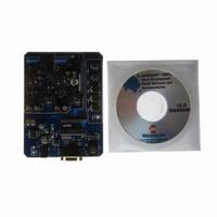
KIT DEMO DSPICDEM SMPS BUCK
Manufacturer
Microchip Technology
Series
dsPIC™r
Datasheets
1.AC164335.pdf
(286 pages)
2.DM300023.pdf
(22 pages)
3.DM300023.pdf
(18 pages)
4.DM300023.pdf
(50 pages)
5.DM300023.pdf
(16 pages)
Specifications of DM300023
Main Purpose
DC/DC, Step Down
Outputs And Type
2, Non-Isolated
Voltage - Input
7 ~ 15V
Regulator Topology
Buck
Board Type
Fully Populated
Utilized Ic / Part
dsPIC30F2020
Processor To Be Evaluated
dsPIC30F202x/1010
Interface Type
RS-232
Lead Free Status / RoHS Status
Lead free / RoHS Compliant
Current - Output
-
Voltage - Output
-
Power - Output
-
Frequency - Switching
-
Lead Free Status / Rohs Status
Lead free / RoHS Compliant
Available stocks
Company
Part Number
Manufacturer
Quantity
Price
Company:

Part Number:
DM300023
Manufacturer:
Microchip Technology
Quantity:
135
Company:
Part Number:
DM300023
Manufacturer:
MICROCHIP
Quantity:
12 000


dsPIC30F1010/202X
1. Module: Power Supply PWM: Dead Time
2. Module: Power Supply PWM: Duty Cycle
DS80290J-page 4
If
(DTC<1:0> = 0 or 1 in the PWMCONx register),
the minimum usable value that can be written to
the dead time registers, DTRx and ALTDTRx, is
0x0010. Writing a value less than 0x0010 will
cause either or both the PWMxH and PWMxL
outputs not to function. The minimum acceptable
dead time value is 0x0010. As a result of this
errata, the minimum usable dead time is 16 ns.
Dead time resolution is 4 ns for dead times greater
than 16 ns.
Work around
The
(DTC<1:0> = 2) or DTRx and ALTDRx must have
a value of 0x0010 or greater. If zero dead time is
required, configure the DTC<1:0> bits in the
PWMCONx register to specify no dead time.
The data sheet indicates that the power supply
PWM module has a 1.1 nsec duty cycle resolution.
This is true for all values of PDCx except the
following:
1. 0x0010 < PDCx < 0x0040
2. (Period - 0x0040) < PDCx < (Period - 0x0010)
In these ranges, duty cycle resolution is 16 ns. The
PWM Period is either the Master Period, PTPER,
or the individual PWM generator period, PHASEx.
Work around
If possible, the system should be designed so that
the PWM generator will operate in the duty cycle
range where the 1.1 ns resolution is possible. For
operation outside this range the design must take
into account the reduced resolution.
dead
dead
time
time
must
functionality
either
be
is
disabled
enabled
3. Module: Power Supply PWM: Special
4. Module: ADC Sample and Hold Timing
Each PWM generator can be configured to
generate a trigger for the ADC module or a trigger
interrupt at any point during the PWM period. The
point in time during the PWM period that the trigger
is set is specified in the TRIGx register for PWM
Individual Trigger, or in the SEVTCMP register for
the Special Event Trigger. The minimum trigger
value in TRIGx or SEVTCMP is 0x0008. Values
below 0x0008 result in a PWM trigger not being
initiated at all. As a result, no ADC sampling or
trigger interrupt will occur.
Work around
If the Special Event Trigger or the Individual
Trigger is implemented, the user should perform a
check in firmware to make sure that TRIGx and/or
SEVTCMP is always greater than 0x0008 and less
than the PWM period.
The dedicated ADC sample and hold circuits can
be triggered by signals from the PWM module. The
dsPIC30F1010/202X data sheet indicates that the
resolution of the PWM-ADC sample and hold
trigger timing is 8 ns. The existing implementation
has a 41.6 ns resolution. In other words, when the
PWM-ADC trigger is fired, an ADC sample may
occur 1 ns to 41.6 ns later.
Work around
None.
Event Trigger and Individual
Trigger
© 2008 Microchip Technology Inc.
Related parts for DM300023
Image
Part Number
Description
Manufacturer
Datasheet
Request
R

Part Number:
Description:
Manufacturer:
Microchip Technology Inc.
Datasheet:
Part Number:
Description:
Manufacturer:
Microchip Technology Inc.
Datasheet:
Part Number:
Description:
Manufacturer:
Microchip Technology Inc.
Datasheet:
Part Number:
Description:
Manufacturer:
Microchip Technology Inc.
Datasheet:
Part Number:
Description:
Manufacturer:
Microchip Technology Inc.
Datasheet:
Part Number:
Description:
Manufacturer:
Microchip Technology Inc.
Datasheet:
Part Number:
Description:
Manufacturer:
Microchip Technology Inc.
Datasheet:
Part Number:
Description:
Manufacturer:
Microchip Technology Inc.
Datasheet: