DM300023 Microchip Technology, DM300023 Datasheet - Page 17
DM300023
Manufacturer Part Number
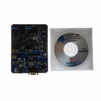
DM300023
Description
KIT DEMO DSPICDEM SMPS BUCK
Manufacturer
Microchip Technology
Series
dsPIC™r
Datasheets
1.AC164335.pdf
(286 pages)
2.DM300023.pdf
(22 pages)
3.DM300023.pdf
(18 pages)
4.DM300023.pdf
(50 pages)
5.DM300023.pdf
(16 pages)
Specifications of DM300023
Main Purpose
DC/DC, Step Down
Outputs And Type
2, Non-Isolated
Voltage - Input
7 ~ 15V
Regulator Topology
Buck
Board Type
Fully Populated
Utilized Ic / Part
dsPIC30F2020
Processor To Be Evaluated
dsPIC30F202x/1010
Interface Type
RS-232
Lead Free Status / RoHS Status
Lead free / RoHS Compliant
Current - Output
-
Voltage - Output
-
Power - Output
-
Frequency - Switching
-
Lead Free Status / Rohs Status
Lead free / RoHS Compliant
Available stocks
Company
Part Number
Manufacturer
Quantity
Price
Company:

Part Number:
DM300023
Manufacturer:
Microchip Technology
Quantity:
135
Company:
Part Number:
DM300023
Manufacturer:
MICROCHIP
Quantity:
12 000


37. Module: PWM Module
© 2008 Microchip Technology Inc.
Note:
Note:
Work around 2:
Instead of executing a PWRSAV #0 instruction to
put the device into Sleep mode, perform a clock
switch to the 512 kHz Low-Power RC (LPRC)
Oscillator with a 64:1 postscaler mode. This
enables the device to operate at 0.002 MIPS,
thereby
consumption of the device. Similarly, instead of
using an interrupt to wake-up the device from
Sleep mode, perform another clock switch back to
the original oscillator source to resume normal
operation. Depending on the device, refer to
Section 7. “Oscillator” (DS70054) or Section
29. “Oscillator” (DS70268) in the “dsPIC30F
Family Reference Manual” (DS70046) for more
details on performing a clock switch operation.
Work around 3:
Instead of executing a PWRSAV #0 instruction to
put the device into Sleep mode, perform a clock
switch to the 32 kHz Low-Power (LP) Oscillator
with a 64:1 postscaler mode. This enables the
device to operate at 0.000125 MIPS, thereby
significantly reducing the current consumption of
the device. Similarly, instead of using an interrupt
to wake-up the device from Sleep mode, perform
another clock switch back to the original oscillator
source to resume normal operation. Depending on
the device, refer to Section 7. “Oscillator”
(DS70054)
(DS70268) in the “dsPIC30F Family Reference
Manual“(DS70046) for more details on performing
a clock switch operation.
The
temperatures below -20ºC. During this condition
the PWM module will relinquish control of the
associated PWM pin and the Port I/O will
determine the state of the pin. In addition, the
PWM module will stop generating the ADC trigger
before the module relinquishes control of the PWM
pins.
Work around
None.
PWM
The above work around is recommended
for users for whom application hardware
changes are not possible.
The above work around is recommended
for users for whom application hardware
changes are possible, and also for users
whose
includes a 32 kHz LP Oscillator crystal.
significantly
or
module
application
Section
may
reducing
hardware
29.
not
the
“Oscillator”
operate
already
current
at
38. Module: PWM Module
39. Module: Power Supply PWM
40. Module: UART Module
41. Module: UART Module
42. Module: SPI Module
43. Module: I
dsPIC30F1010/202X
In Push-Pull mode, with immediate updates
enabled, the PWM pins may become swapped.
Work around
If using the PWM module in Push-Pull mode,
immediate updates must be disabled.
The dead time registers (DTRx/ALTDTRx) must be
modified only when the PWM is not running.
Adjusting the dead time “on-the-fly” can result in
an unpredictable glitch on the PWM output, which
may cause shoot-through.
Work around
None.
When the UART is configured for IR interface
operations (UxMODE<9:8> = 11), the 16x baud
clock signal on the BCLK pin is present only when
the module is transmitting. The pin is idle at all
other times.
Work around
Configure one of the output compare modules to
generate the required baud clock signal when the
UART is receiving data or in an idle state.
When the UART is in 4x mode (BRGH = 1) and
using two Stop bits (STSEL = 1), it may sample the
first Stop bit instead of the second one.
This issue does not affect the other UART
configurations.
Work around
Use the 16x baud rate option (BRGH = 0) and
adjust the baud rate accordingly.
Setting the DISSCK bit in the SPIxCON1 register
does not allow the user application to use the SCK
pin as a general purpose I/O pin.
Work around
None.
The BCL bit in I2CSTAT can be cleared only with
16-bit operation and can be corrupted with 1-bit or
8-bit operations on I2CSTAT.
Work around
Use 16-bit operations to clear BCL.
2
C Module
DS80290J-page 17
Related parts for DM300023
Image
Part Number
Description
Manufacturer
Datasheet
Request
R

Part Number:
Description:
Manufacturer:
Microchip Technology Inc.
Datasheet:
Part Number:
Description:
Manufacturer:
Microchip Technology Inc.
Datasheet:
Part Number:
Description:
Manufacturer:
Microchip Technology Inc.
Datasheet:
Part Number:
Description:
Manufacturer:
Microchip Technology Inc.
Datasheet:
Part Number:
Description:
Manufacturer:
Microchip Technology Inc.
Datasheet:
Part Number:
Description:
Manufacturer:
Microchip Technology Inc.
Datasheet:
Part Number:
Description:
Manufacturer:
Microchip Technology Inc.
Datasheet:
Part Number:
Description:
Manufacturer:
Microchip Technology Inc.
Datasheet: