AD9272-65EBZ Analog Devices Inc, AD9272-65EBZ Datasheet - Page 8
AD9272-65EBZ
Manufacturer Part Number
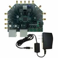
AD9272-65EBZ
Description
BOARD EVAL AD9272
Manufacturer
Analog Devices Inc
Specifications of AD9272-65EBZ
Design Resources
Powering AD9272 with ADP5020 Switching Regulator PMU for Increased Efficiency (CN0135)
Number Of Adc's
8
Number Of Bits
12
Sampling Rate (per Second)
65M
Data Interface
Serial
Inputs Per Adc
1 Differential
Input Range
733 mVpp
Power (typ) @ Conditions
1.69W @ 65MSPS
Voltage Supply Source
Analog and Digital
Operating Temperature
-40°C ~ 85°C
Utilized Ic / Part
AD9272
Silicon Manufacturer
Analog Devices
Application Sub Type
ADC
Kit Application Type
Data Converter
Silicon Core Number
AD9272
Kit Contents
Board
Development Tool Type
Hardware - Eval/Demo Board
Rohs Compliant
Yes
Lead Free Status / RoHS Status
Lead free / RoHS Compliant


UG-001
4.
5.
Program the HSC-ADC-EVALCZ board’s FPGA to a setting
other than the default setting as described in Step 3. Then
expand the VisualAnalog display and click the Settings
button in the ADC Data Capture block (see Figure 6). The
ADC Data Capture Settings box opens (see Figure 7).
Select the Board Settings tab and browse to the appropriate
programming file. If you are using an encode rate <28 MSPS,
select Octal_Low_Speed.bin. If you are using an encode
rate >28 MSPS, select Octal_High_Speed.bin. Next, click
Program; the DONE LED in the HSC-ADC-EVALCZ board
should then turn on. If more than two channels are required
to be displayed, select Octal_High_8-Channel_synchronous
Capture.bin. This canvas allows the user to display all the
channels at once. The drawback is that each FFT display is
only 8k points.
Exit the ADC Data Capture Settings box by clicking OK.
Figure 7. ADC Data Capture Settings Window, Board Settings Tab
SETTINGS
BUTTON
Figure 6. VisualAnalog, Main Window
COLLAPSE DISPLAY BUTTON
Rev. 0 | Page 8 of 24
Setting Up the SPI Controller
After the ADC data capture board setup is completed, set up the
SPI Controller using the following procedure:
1.
2.
3.
Open the SPI Controller software by going to the Start
menu or double-clicking the SPI Controller software
desktop icon. If prompted for a configuration file, select
the appropriate one. If not, check the title bar of the
window to determine which configuration is loaded. If
necessary, choose Cfg Open from the File menu and select
the appropriate one. Note that the CHIP ID(1) field should
be filled to indicate whether the correct SPI Controller
configuration file is loaded or not (see Figure 8).
Click the New DUT button in the SPI Controller.
In the Global tab of the SPI Controller, find the CHIP
GRADE(2) box. Use the drop-down box to select the
correct speed grade, if necessary. See the AD9272 or AD9273
data sheet, the AN-878 Application Note, and the AN-877
Application Note for reference.
NEW DUT BUTTON
Figure 9. SPI Controller, New DUT Button
Figure 8. SPI Controller, CHIP ID(1) Box
Evaluation Board User Guide
Related parts for AD9272-65EBZ
Image
Part Number
Description
Manufacturer
Datasheet
Request
R

Part Number:
Description:
±1.7g Dual-Axis IMEMS Accelerometer Evaluation Board
Manufacturer:
Analog Devices Inc
Datasheet:

Part Number:
Description:
Inertial Sensor Evaluation System
Manufacturer:
Analog Devices Inc
Datasheet:
Part Number:
Description:
Manufacturer:
Analog Devices Inc
Datasheet:
Part Number:
Description:
Manufacturer:
Analog Devices Inc
Datasheet:
Part Number:
Description:
Manufacturer:
Analog Devices Inc
Datasheet:
Part Number:
Description:
Manufacturer:
Analog Devices Inc
Datasheet:
Part Number:
Description:
Manufacturer:
Analog Devices Inc
Datasheet:
Part Number:
Description:
Manufacturer:
Analog Devices Inc
Datasheet:
Part Number:
Description:
Manufacturer:
Analog Devices Inc
Datasheet:
Part Number:
Description:
Manufacturer:
Analog Devices Inc
Datasheet:
Part Number:
Description:
Manufacturer:
Analog Devices Inc
Datasheet:
Part Number:
Description:
Manufacturer:
Analog Devices Inc
Datasheet:
Part Number:
Description:
Manufacturer:
Analog Devices Inc
Datasheet: