AD9272-65EBZ Analog Devices Inc, AD9272-65EBZ Datasheet
AD9272-65EBZ
Specifications of AD9272-65EBZ


Related parts for AD9272-65EBZ


AD9272-65EBZ Summary of contents
Page 1
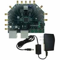
... HSC-ADC-EVALCZ FPGA-based data capture kit For CW Doppler mode: spectrum analyzer For CW Doppler mode: dc voltage source w/100 mA each Figure 1. AD9272-65EBZ/AD9272-80KITZ/AD9273-50EBZ Evaluation Board and HSC-ADC-EVALCZ Data Capture Board Please see the last page for an important warning and disclaimers. Evaluation Board User Guide DOCUMENTS NEEDED ...
Page 2
UG-001 TABLE OF CONTENTS Features .............................................................................................. 1 Equipment Needed ........................................................................... 1 Documents Needed .......................................................................... 1 Software Needed ............................................................................... 1 General Description ......................................................................... 1 Typical Measurement Setup ............................................................ 1 Revision History ............................................................................... 2 Evaluation Board Hardware ............................................................ 3 Power Supplies .............................................................................. ...
Page 3
... Figure 2 shows the typical bench characterization setup used to evaluate the ac performance of the AD9272/AD9273 critical that the signal sources used for the analog input and clock have very low phase noise (<1 ps rms jitter) to realize the optimum performance of the signal chain. ...
Page 4
UG-001 WALL OUTLET 100V TO 240V AC 47Hz TO 63Hz SWITCHING POWER SUPPLY SWITCHING POWER SUPPLY SIGNAL SYNTHESIZER ANALOG INPUT SPECTRUM ANALYZER CW OUTPUT AGILENT POWER SUPPLY GAIN CONTROL INPUT Evaluation Board User Guide MAX SIGNAL SYNTHESIZER ...
Page 5
... Upon shipment, the CWD0+/CWD0−, CWD1+/CWD1−, CWD6+/CWD6−, and CWD7+/CWD7− outputs are properly biased and ready to use with the and phase shifter. The AD9272/AD9273 evaluation board simply snaps into place on the AD8339 evaluation board (AD8339- EVALZ). Remove the jumpers connected to P3A and P4A on ...
Page 6
... UG-001 between the AD9272/AD9273 CWDx± outputs and the AD8339 inputs. DOUTx+, DOUTx− alternative data capture method to the setup described in Figure 2 is used, optional receiver terminations, R701 to R710, can be installed next to the high speed backplane connector. Evaluation Board User Guide ...
Page 7
... Evaluation Board User Guide EVALUATION BOARD SOFTWARE QUICK START PROCEDURES This section provides quick start procedures for using the AD9272/ AD9273 either on the evaluation board system level design. Both the default and optional settings are described. CONFIGURING THE BOARD Before using the software for testing, configure the evaluation board as follows: 1 ...
Page 8
... In the Global tab of the SPI Controller, find the CHIP GRADE(2) box. Use the drop-down box to select the correct speed grade, if necessary. See the AD9272 or AD9273 data sheet, the AN-878 Application Note, and the AN-877 Application Note for reference. Rev Page ...
Page 9
... Figure 10. SPI Controller, CHIP GRADE(2) Box 4. In the ADCBase 0 tab of the SPI Controller, find the HIGHPASS(2B) box. Click Manual Tune to calibrate the antialiasing filter. See the AD9272 or AD9273 data sheet, the AN-878 Application Note, and the AN-877 Application Note for reference. Figure 11. SPI Controller, HIGHPASS(2B) Box 5 ...
Page 10
... Note that the CWD0±/CWD1±/CWD6±/CWD7± outputs are configured and biased to interface with the evaluation board. The AD9272/AD9273 is specially designed to snap onto the AD8339 evaluation board to allow the user to evaluate a larger portion of this common signal chain. For detailed instructions about enabling this function, send an email to highspeed ...
Page 11
Evaluation Board User Guide Figure 18. SPI Controller, MODES(8) Box 7. In the ADC x tab of the SPI Controller, where x is the channel to which an analog input is applied, find the CROSSPOINT SWITCH(2D) box. From the Crosspoint ...
Page 12
UG-001 EVALUATION BOARD SCHEMATICS AND ARTWORK Figure 21. Evaluation Board Schematic, DUT Analog Input Circuits Rev Page Evaluation Board User Guide 07782-005 ...
Page 13
Evaluation Board User Guide Figure 22. Evaluation Board Schematic, DUT Analog Input Circuits (Continued) Rev Page UG-001 07782-006 ...
Page 14
UG-001 Figure 23. Evaluation Board Schematic, DUT, VREF, and Decoupling Rev Page Evaluation Board User Guide 07782-007 ...
Page 15
Evaluation Board User Guide Figure 24. Evaluation Board Schematic, Clock, SPI, and Gain Circuits Rev Page UG-001 07782-008 ...
Page 16
UG-001 Figure 25. Evaluation Board Schematic, Power Supply, CW Doppler, Digital Output Interface Evaluation Board User Guide Rev Page 07782-009 ...
Page 17
Evaluation Board User Guide Figure 26. Evaluation Board Layout, Top Side Rev Page UG-001 ...
Page 18
UG-001 Figure 27. Evaluation Board Layout, Ground Plane (Layer 2) Rev Page Evaluation Board User Guide ...
Page 19
Evaluation Board User Guide Figure 28. Evaluation Board Layout, Power Plane (Layer 3) Rev Page UG-001 ...
Page 20
UG-001 Figure 29. Evaluation Board Layout, Power Plane (Layer 4) Rev Page Evaluation Board User Guide ...
Page 21
Evaluation Board User Guide Figure 30. Evaluation Board Layout, Ground Plane (Layer 5) Rev Page UG-001 ...
Page 22
UG-001 Figure 31. Evaluation Board Layout, Bottom Side Rev Page Evaluation Board User Guide ...
Page 23
Evaluation Board User Guide ORDERING INFORMATION BILL OF MATERIALS Table 1. Item Qty Reference Designator 1 79 C101, C102, C106, C110, C111, C115, C120, C121, C125, C130, C131, C136, C201, C202, C206, C210, C211, C215, C220, C221, C225, C230, C231, ...
Page 24
... Panasonic ERJ-2RKF1130X Copal CT94EW103 Minicircuits ADT1-1WT+ Minicircuits ADTT4-1+ Fairchild NC7WZ07P6X Fairchild NC7WZ16P6X Analog Devices ADR130BUJZ-R2 Analog Devices AD9515BCPZ Analog Devices AD812ARZ Analog Devices ADP3335ACPZ-2.5R7 Analog Devices ADP3339AKCZ-1.8-R7 Analog Devices ADP3339AKCZ-3.3-R7 Analog Devices ADP3339AKCZ-3-RL7 Analog Devices AD8138ARZ Analog Devices AD9273BSVZ-50, AD9272BSVZ-65, AD9272BSVZ-80 ...