AD9272-65EBZ Analog Devices Inc, AD9272-65EBZ Datasheet - Page 7
AD9272-65EBZ
Manufacturer Part Number
AD9272-65EBZ
Description
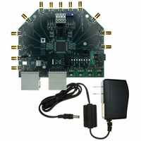
BOARD EVAL AD9272
Manufacturer
Analog Devices Inc
Specifications of AD9272-65EBZ
Design Resources
Powering AD9272 with ADP5020 Switching Regulator PMU for Increased Efficiency (CN0135)
Number Of Adc's
8
Number Of Bits
12
Sampling Rate (per Second)
65M
Data Interface
Serial
Inputs Per Adc
1 Differential
Input Range
733 mVpp
Power (typ) @ Conditions
1.69W @ 65MSPS
Voltage Supply Source
Analog and Digital
Operating Temperature
-40°C ~ 85°C
Utilized Ic / Part
AD9272
Silicon Manufacturer
Analog Devices
Application Sub Type
ADC
Kit Application Type
Data Converter
Silicon Core Number
AD9272
Kit Contents
Board
Development Tool Type
Hardware - Eval/Demo Board
Rohs Compliant
Yes
Lead Free Status / RoHS Status
Lead free / RoHS Compliant


Evaluation Board User Guide
EVALUATION BOARD SOFTWARE QUICK START PROCEDURES
This section provides quick start procedures for using the AD9272/
AD9273 either on the evaluation board or in a system level
design. Both the default and optional settings are described.
CONFIGURING THE BOARD
Before using the software for testing, configure the evaluation
board as follows:
1.
2.
3.
4.
5.
6.
7.
USING THE SOFTWARE FOR TESTING
Setting Up the ADC Data Capture Block
After configuring the board, set up the ADC data capture block
using the following steps:
1.
Connect the evaluation board to the data capture board as
shown in Figure 1 and Figure 2.
Connect one 6 V, 2.5 A switching power supply (such as
the CUI Inc. EPS060250UH-PHP-SZ supplied) to the
AD9272/AD9273 board.
Connect one 6 V, 2.5 A switching power supply (such as
the CUI EPS060250UH-PHP-SZ supplied) to the HSC-
ADC-EVALCZ board.
Connect the HSC-ADC-EVALCZ board (J6) to the PC
with a USB cable.
On the ADC evaluation board, place jumpers on all four
pin pairs of J601 to connect the SPI bus.
On the ADC evaluation board, ensure that J401 (OSC_EN)
is jumpered to the on setting to use the on-board 50 MHz/
65 MHz/80 MHz Valpey Fisher VFAC3 oscillator.
On the ADC evaluation board, use a clean signal generator
with low phase noise to provide an input signal to the
desired channel. Use a 1 m, shielded, RG-58, 50 Ω coaxial
cable to connect the signal generator. For best results, use a
narrow-band band-pass filter with 50 Ω terminations and
an appropriate center frequency. (Analog Devices uses
TTE, Allen Avionics, and K&L band-pass filters.)
Open VisualAnalog™ on a PC. AD9272 or AD9273 should
be listed in the status bar of the New Canvas window.
Select the template that corresponds to the type of testing
to be performed (see Figure 3).
Rev. 0 | Page 7 of 24
2.
3.
After the template is selected, a message appears, asking if
the default configuration can be used to program the FPGA
(see Figure 4). Click Yes, and the window closes.
If a different program is desired, follow Step 3.
To view different channels or change features to settings
other than the default settings, click the Expand Display
button. This is located on the bottom right corner of the
window, as shown in Figure 5.
This process is described in the AN-905 Application Note,
VisualAnalog Converter Evaluation Tool Version 1.0 User
Manual. After you are finished, click the Collapse Display
button (see Figure 6).
Figure 5. VisualAnalog Window Toolbar, Collapsed Display
Figure 4. VisualAnalog, Default Configuration Message
Figure 3. VisualAnalog, New Canvas Window
EXPAND DISPLAY BUTTON
UG-001
Related parts for AD9272-65EBZ
Image
Part Number
Description
Manufacturer
Datasheet
Request
R

Part Number:
Description:
±1.7g Dual-Axis IMEMS Accelerometer Evaluation Board
Manufacturer:
Analog Devices Inc
Datasheet:

Part Number:
Description:
Inertial Sensor Evaluation System
Manufacturer:
Analog Devices Inc
Datasheet:
Part Number:
Description:
Manufacturer:
Analog Devices Inc
Datasheet:
Part Number:
Description:
Manufacturer:
Analog Devices Inc
Datasheet:
Part Number:
Description:
Manufacturer:
Analog Devices Inc
Datasheet:
Part Number:
Description:
Manufacturer:
Analog Devices Inc
Datasheet:
Part Number:
Description:
Manufacturer:
Analog Devices Inc
Datasheet:
Part Number:
Description:
Manufacturer:
Analog Devices Inc
Datasheet:
Part Number:
Description:
Manufacturer:
Analog Devices Inc
Datasheet:
Part Number:
Description:
Manufacturer:
Analog Devices Inc
Datasheet:
Part Number:
Description:
Manufacturer:
Analog Devices Inc
Datasheet:
Part Number:
Description:
Manufacturer:
Analog Devices Inc
Datasheet:
Part Number:
Description:
Manufacturer:
Analog Devices Inc
Datasheet: