EVAL-AD7708EBZ Analog Devices Inc, EVAL-AD7708EBZ Datasheet - Page 26
EVAL-AD7708EBZ
Manufacturer Part Number
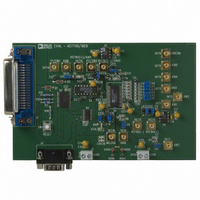
EVAL-AD7708EBZ
Description
BOARD EVAL FOR AD7708
Manufacturer
Analog Devices Inc
Specifications of EVAL-AD7708EBZ
Number Of Adc's
1
Number Of Bits
16
Sampling Rate (per Second)
1.37k
Data Interface
Serial
Inputs Per Adc
8 Single or 4 Differential
Input Range
±2.5 V
Power (typ) @ Conditions
3.84mW @ 3 V
Voltage Supply Source
Analog and Digital
Operating Temperature
-40°C ~ 85°C
Utilized Ic / Part
AD7708
Lead Free Status / RoHS Status
Lead free / RoHS Compliant
Other names
EVAL-AD7708EB
EVAL-AD7708EB
EVAL-AD7708EB


Status Register (A3, A2, A1, A0 = 0, 0, 0, 0; Power-On-Reset = 00Hex)
The ADC Status Register is an 8-bit read-only register. To access the ADC Status Register, the user must write to the Communica-
tions Register selecting the next operation to be a read and load Bits A3-A0 with 0, 0, 0,0. Table XIV outlines the bit designations
for the Status Register. SR0 through SR7 indicate the bit location, SR denoting the bits are in the Status Register. SR7 denotes the
first bit of the data stream. The number in brackets indicates the power-on/reset default status of that bit.
Bit
Location
SR7
SR6
SR5
SR4
SR3
SR2
SR1
SR0
AD7708/AD7718
R
D
S 7
Y
R
(
) 0
Bit
Mnemonic Description
RDY
0
CAL
0
ERR
0
0
LOCK
0
S
R
(
) 0
6
Ready Bit for the ADC
Set when data is transferred to the ADC data registers or on completion of calibration cycle. The RDY
bit is cleared automatically a period of time before the data register is updated with a new conversion
result or after the ADC data register has been read. This bit is also cleared by a write to the mode bits to
indicate a conversion or calibration. The RDY pin is the complement of the RDY bit.
Bit is automatically cleared. Reserved for future use
Calibration Status Bit
Set to indicate completion of calibration. It is set at the same time that the RDY is set high.
Cleared by a write to the mode bits to start another ADC conversion or calibration.
This bit is automatically cleared. Reserved for future use
ADC Error Bit
Set to indicate that the result written to the ADC data register has been clamped to all zeros or all ones.
After a calibration this bit also flags error conditions that caused the calibration registers not to be
written. Error sources include Overrange.
Cleared by a write to the mode bits to initiate a conversion or calibration.
This bit is automatically cleared. Reserved for future use
This bit is automatically cleared. Reserved for future use
PLL Lock Status Bit.
Set if the PLL has locked onto the 32.768 kHz crystal oscillator clock. If the user is worried about
exact sampling frequencies etc., the LOCK bit should be interrogated and the result discarded if the
LOCK bit is zero.
C
A
S
L
R
5
(
) 0
Table XIV. Status Register Bit Designations
0
S
R
(
) 0
4
E
R
S
R
R
3
(
) 0
0
S
R
(
) 0
2
0
S
R
(
) 0
1
L
O
S
C
R
K
0
(
) 0
Related parts for EVAL-AD7708EBZ
Image
Part Number
Description
Manufacturer
Datasheet
Request
R


Part Number:
Description:
BOARD EVAL FOR SI270X-A
Manufacturer:
Silicon Laboratories Inc
Datasheet:

Part Number:
Description:
BUCK CONV REF DESIGN KIT IP1201
Manufacturer:
International Rectifier
Datasheet:
Part Number:
Description:
BOARD DEMO SYNC DUAL BUCK CNVTER
Manufacturer:
International Rectifier
Datasheet:
Part Number:
Description:
BOARD DEMO SYNC BUCK CONVETER
Manufacturer:
International Rectifier
Datasheet:

Part Number:
Description:
EVALBOARD/EB Omnidirectional microphone - Analog
Manufacturer:
Analog Devices
Datasheet:
Part Number:
Description:
EVALBOARD/EB Omnidirectional microphone - Analog
Manufacturer:
Analog Devices
Datasheet:


Part Number:
Description:
BOARD EVAL LED DRIVER LT3756
Manufacturer:
Linear Technology
Datasheet:

Part Number:
Description:
BOARD EVAL FOR AD7741/7742
Manufacturer:
Analog Devices Inc
Datasheet:

Part Number:
Description:
±1.7g Dual-Axis IMEMS Accelerometer Evaluation Board
Manufacturer:
Analog Devices Inc
Datasheet:

Part Number:
Description:
IC MULTIPLIER ANALOG 8-SOIC T/R
Manufacturer:
Analog Devices Inc
Datasheet:

Part Number:
Description:
IC ANALOG MULTIPLIER 8-DIP
Manufacturer:
Analog Devices Inc
Datasheet:
Part Number:
Description:
IC ANALOG MULTIPLIER 8-SOIC
Manufacturer:
Analog Devices Inc
Datasheet:
Part Number:
Description:
IC ANALOG MULTIPLIER 8-DIP
Manufacturer:
Analog Devices Inc
Datasheet: