MCP3221DM-PCTL Microchip Technology, MCP3221DM-PCTL Datasheet - Page 16
MCP3221DM-PCTL
Manufacturer Part Number
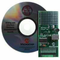
MCP3221DM-PCTL
Description
BOARD DEMO FOR PICTAIL MCP3221
Manufacturer
Microchip Technology
Series
PICtail™r
Type
A/Dr
Datasheets
1.MCP3221A5T-IOT.pdf
(28 pages)
2.MCP3221DM-PCTL.pdf
(20 pages)
3.MCP3221DM-PCTL.pdf
(20 pages)
Specifications of MCP3221DM-PCTL
Number Of Adc's
1
Number Of Bits
12
Sampling Rate (per Second)
22.3k
Data Interface
Serial
Inputs Per Adc
1 Single Ended
Voltage Supply Source
Single Supply
Operating Temperature
-40°C ~ 85°C
Utilized Ic / Part
MCP3221
Product
Data Conversion Development Tools
Resolution
12 bit
Interface Type
USB
Silicon Manufacturer
Microchip
Silicon Core Number
MCP3221
Kit Application Type
Data Converter
Application Sub Type
ADC
Silicon Family Name
PICtail
Kit Contents
Board Cables CD Docs
Rohs Compliant
Yes
For Use With/related Products
MCP3221
Lead Free Status / RoHS Status
Contains lead / RoHS non-compliant
Lead Free Status / RoHS Status
Lead free / RoHS Compliant, Contains lead / RoHS non-compliant
Available stocks
Company
Part Number
Manufacturer
Quantity
Price
Company:

Part Number:
MCP3221DM-PCTL
Manufacturer:
MICROCHIP
Quantity:
12 000


MCP3221
5.2
The address byte is the first byte received following the
START condition from the master device. The first part
of the control byte consists of a 4-bit device code, which
is set to 1001 for the MCP3221. The device code is fol-
lowed by three address bits: A2, A1 and A0. The default
address bits are 101. Contact the Microchip factory for
additional address bit options. The address bits allow
up to eight MCP3221 devices on the same bus and are
used to determine which device is accessed.
The eighth bit of the slave address determines if the
master device wants to read conversion data or write to
the MCP3221. When set to a ‘1’, a read operation is
selected. When set to a ‘0’, a write operation is
selected. There are no writable registers on the
MCP3221. Therefore, this bit must be set to a ’1’ in
order to initiate a conversion.
The MCP3221 is a slave device that is compatible with
the I
connection diagram is shown in Figure 6-2. Communi-
cation is initiated by the microcontroller (master
device), which sends a START bit followed by the
address byte.
On completion of the conversion(s) performed by the
MCP3221, the microcontroller must send a STOP bit to
end communication.
The last bit in the device address byte is the R/W bit.
When this bit is a logic ‘1’, a conversion will be exe-
cuted. Setting this bit to logic ‘0’ will also result in an
“acknowledge” (ACK) from the MCP3221, with the
device then releasing the bus. This can be used for
device polling. Refer to Section 6.3 “Device Polling”,
“Device Polling”, for more information.
FIGURE 5-2:
DS21732C-page 16
Note 1: Contact Microchip for additional address bits.
2
C 2-wire serial interface protocol. A hardware
START
1
Device Addressing
Device Code
0
SLAVE ADDRESS
0
Device Addressing.
1
Address Bits(1)
1
READ/WRITE
0
1
R/W A
5.3
This section will describe the details of communicating
with the MCP3221 device. Initiating the sample-and-
hold acquisition, reading the conversion data and
executing multiple conversions will be discussed.
5.3.1
The acquisition and conversion of the input signal
begins with the falling edge of the R/W bit of the
address byte. At this point, the internal clock initiates
the sample, hold and conversion cycle, all of which are
internal to the ADC.
FIGURE 5-3:
Address Byte.
FIGURE 5-4:
Continuous Conversions.
SDA
SCL
SDA
SCL
Executing a Conversion
Start
D8
Bit
17 18 19 20 21 22 23 24 25 26
INITIATING THE SAMPLE AND
HOLD
1
1
D7
Device bits
0
D6 D5 D4
2
Lower Data Byte (n)
t
Initiating the Conversion,
Initiating the Conversion,
ACQ
initiated here
t
© 2006 Microchip Technology Inc.
ACQ
initiated here
3
0
Address Byte
+ t
+ t
4
1 A2 A1 A0 R/W
CONV
CONV
Address bits
D3 D2 D2
5
is
6
is
7
D0
8
9
Related parts for MCP3221DM-PCTL
Image
Part Number
Description
Manufacturer
Datasheet
Request
R

Part Number:
Description:
Manufacturer:
Microchip Technology Inc.
Datasheet:
Part Number:
Description:
Manufacturer:
Microchip Technology Inc.
Datasheet:
Part Number:
Description:
Manufacturer:
Microchip Technology Inc.
Datasheet:
Part Number:
Description:
Manufacturer:
Microchip Technology Inc.
Datasheet:
Part Number:
Description:
Manufacturer:
Microchip Technology Inc.
Datasheet:
Part Number:
Description:
Manufacturer:
Microchip Technology Inc.
Datasheet:
Part Number:
Description:
Manufacturer:
Microchip Technology Inc.
Datasheet:
Part Number:
Description:
Manufacturer:
Microchip Technology Inc.
Datasheet: