MCP3221DM-PCTL Microchip Technology, MCP3221DM-PCTL Datasheet - Page 14
MCP3221DM-PCTL
Manufacturer Part Number
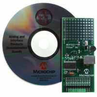
MCP3221DM-PCTL
Description
BOARD DEMO FOR PICTAIL MCP3221
Manufacturer
Microchip Technology
Series
PICtail™r
Type
A/Dr
Datasheets
1.MCP3221A5T-IOT.pdf
(28 pages)
2.MCP3221DM-PCTL.pdf
(20 pages)
3.MCP3221DM-PCTL.pdf
(20 pages)
Specifications of MCP3221DM-PCTL
Number Of Adc's
1
Number Of Bits
12
Sampling Rate (per Second)
22.3k
Data Interface
Serial
Inputs Per Adc
1 Single Ended
Voltage Supply Source
Single Supply
Operating Temperature
-40°C ~ 85°C
Utilized Ic / Part
MCP3221
Product
Data Conversion Development Tools
Resolution
12 bit
Interface Type
USB
Silicon Manufacturer
Microchip
Silicon Core Number
MCP3221
Kit Application Type
Data Converter
Application Sub Type
ADC
Silicon Family Name
PICtail
Kit Contents
Board Cables CD Docs
Rohs Compliant
Yes
For Use With/related Products
MCP3221
Lead Free Status / RoHS Status
Contains lead / RoHS non-compliant
Lead Free Status / RoHS Status
Lead free / RoHS Compliant, Contains lead / RoHS non-compliant
Available stocks
Company
Part Number
Manufacturer
Quantity
Price
Company:

Part Number:
MCP3221DM-PCTL
Manufacturer:
MICROCHIP
Quantity:
12 000


MCP3221
4.5
In the ideal A/D converter transfer function, each code
has a uniform width. That is, the difference in analog
input voltage is constant from one code transition point
to the next. Differential nonlinearity (DNL) specifies the
deviation of any code in the transfer function from an
ideal code width of 1 LSB. The DNL is determined by
subtracting the locations of successive code transition
points after compensating for any gain and offset
errors. A positive DNL implies that a code is longer than
the ideal code width, while a negative DNL implies that
a code is shorter than the ideal width.
4.6
Integral nonlinearity (INL) is a result of cumulative DNL
errors and specifies how much the overall transfer
function deviates from a linear response. The method
of measurement used in the MCP3221 A/D converter
to determine INL is the “end-point” method.
4.7
Offset error is defined as a deviation of the code transi-
tion points that are present across all output codes.
This has the effect of shifting the entire A/D transfer
function. The offset error is measured by finding the dif-
ference between the actual location of the first code
transition and the desired location of the first transition.
The ideal location of the first code transition is located
at 1/2 LSB above V
DS21732C-page 14
Differential Non-Linearity (DNL)
Integral Non-Linearity (INL)
Offset Error
SS
.
4.8
The gain error determines the amount of deviation from
the ideal slope of the A/D converter transfer function.
Before the gain error is determined, the offset error is
measured and subtracted from the conversion result.
The gain error can then be determined by finding the
location of the last code transition and comparing that
location to the ideal location. The ideal location of the
last code transition is 1.5 LSBs below full-scale or V
4.9
The average amount of current over the time required
to perform a 12-bit conversion.
4.10
The average amount of current over the time required
to monitor the I
sumes while it is not being addressed is referred to as
“Active Bus” current.
4.11
The average amount of current required while no con-
version is occurring and while no data is being output
(i.e., SCL and SDA lines are quiet).
4.12
I
100 kHz.
4.13
I
400 kHz.
2
2
C specification where the frequency of SCL is
C specification where the frequency of SCL is
Gain Error
Conversion Current (I
Active Bus Current (I
Standby Current (I
I
I
2
2
C Standard Mode Timing
C Fast Mode Timing
2
C bus. Any current the device con-
© 2006 Microchip Technology Inc.
DDS
DDA
DD
)
)
)
DD
.
Related parts for MCP3221DM-PCTL
Image
Part Number
Description
Manufacturer
Datasheet
Request
R

Part Number:
Description:
Manufacturer:
Microchip Technology Inc.
Datasheet:
Part Number:
Description:
Manufacturer:
Microchip Technology Inc.
Datasheet:
Part Number:
Description:
Manufacturer:
Microchip Technology Inc.
Datasheet:
Part Number:
Description:
Manufacturer:
Microchip Technology Inc.
Datasheet:
Part Number:
Description:
Manufacturer:
Microchip Technology Inc.
Datasheet:
Part Number:
Description:
Manufacturer:
Microchip Technology Inc.
Datasheet:
Part Number:
Description:
Manufacturer:
Microchip Technology Inc.
Datasheet:
Part Number:
Description:
Manufacturer:
Microchip Technology Inc.
Datasheet: