EVAL6226QR STMicroelectronics, EVAL6226QR Datasheet - Page 19
EVAL6226QR
Manufacturer Part Number
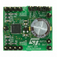
EVAL6226QR
Description
EVAL BOARD FOR L6226Q
Manufacturer
STMicroelectronics
Type
Motor / Motion Controllers & Driversr
Specifications of EVAL6226QR
Mfg Application Notes
EVAL6226QR AppNote
Main Purpose
Power Management, Motor Control
Embedded
No
Utilized Ic / Part
L6226Q
Primary Attributes
Stepper, Bi-Polar/2-Phase, 1A DC, 8 ~ 52V Output
Secondary Attributes
Thermal Protection, Internal Free Wheeling Diodes
Board Size
27 mm x 24.5 mm
Maximum Operating Temperature
+ 125 C
Operating Supply Voltage
8 V to 52 V
Product
Power Management Modules
Dimensions
27 mm x 24.5 mm
Lead Free Status / RoHS Status
Lead free / RoHS Compliant
For Use With/related Products
L6226Q
Other names
497-6816


L6226Q
6
Paralleled operation
The outputs of the L6226Q can be paralleled to increase the output current capability or
reduce the power dissipation in the device at a given current level. It must be noted,
however, that the internal wire bond connections from the die to the power or sense pins of
the package must carry current in both of the associated half bridges. When the two halves
of one full bridge (for example OUT1
current rating is not increased since the total current must still flow through one bond wire on
the power supply or sense pin. In addition the over current detection senses the sum of the
current in the upper devices of each bridge (A or B) so connecting the two halves of one
bridge in parallel does not increase the over current detection threshold.
For most applications the recommended configuration is half bridge 1 of bridge A paralleled
with the half bridge 1 of the bridge B, and the same for the half bridges 2 as shown in
Figure
R
When connected in this configuration the over current detection circuit, which senses the
current in each bridge (A and B), will sense the current in upper devices connected in
parallel independently and the sense circuit with the lowest threshold will trip first. With the
enables connected in parallel, the first detection of an over current in either upper DMOS
device will turn of both bridges. Assuming that the two DMOS devices share the current
equally, the resulting over current detection threshold will be twice the minimum threshold
set by the resistors R
In this configuration the resulting bridge has the following characteristics.
●
●
●
●
DS(on)
Equivalent device: full bridge
R
2.8 A max RMS load current
5.6 A max OCD threshold
DS(on)
15. The current in the two devices connected in parallel will share very well since the
of the devices on the same die is well matched.
0.37 Ω typ. value @ T
CLA
or R
CLB
Doc ID 14335 Rev 5
in
J
Figure
= 25 °C
A
and OUT2
15. It is recommended to use R
A
) are connected in parallel, the peak
Paralleled operation
CLA
= R
CLB
.
19/29
Related parts for EVAL6226QR
Image
Part Number
Description
Manufacturer
Datasheet
Request
R

Part Number:
Description:
ENERCHIP CC EVAL KIT
Manufacturer:
Cymbet Corporation
Datasheet:

Part Number:
Description:
BOARD EVAL FOR AD976
Manufacturer:
Analog Devices Inc
Datasheet:

Part Number:
Description:
BOARD EVAL FOR ADXL345
Manufacturer:
Analog Devices Inc
Datasheet:

Part Number:
Description:
ENERCHIP CC SEH EVAL KIT
Manufacturer:
Cymbet Corporation
Datasheet:

Part Number:
Description:
ENERCHIP EP ENERGY HARVEST EVAL
Manufacturer:
Cymbet Corporation
Datasheet:

Part Number:
Description:
EVAL BOARD FOR TW6864-LB2-GR
Manufacturer:
Intersil
Datasheet:
Part Number:
Description:
EVAL BOARD FOR TW8816-LB3-GR
Manufacturer:
Intersil
Datasheet:
Part Number:
Description:
EVAL BOARD FOR TW8817-TA3-GRS
Manufacturer:
Intersil
Datasheet:

Part Number:
Description:
EVALUATION MODULE FOR ADUM4160
Manufacturer:
Analog Devices Inc
Datasheet:

Part Number:
Description:
BOARD EVALUATION ADCMP581BCP
Manufacturer:
Analog Devices Inc
Datasheet:
Part Number:
Description:
BOARD EVALUATION ADM1041
Manufacturer:
Analog Devices Inc
Datasheet:

Part Number:
Description:
EVAL BOARD FOR STM32F107VCT
Manufacturer:
STMicroelectronics
Datasheet:
Part Number:
Description:
BOARD EVAL FOR AD1954
Manufacturer:
Analog Devices Inc
Datasheet:
Part Number:
Description:
BOARD EVAL FOR AD1955
Manufacturer:
Analog Devices Inc
Datasheet:

Part Number:
Description:
BOARD EVAL FOR AD7655
Manufacturer:
Analog Devices Inc
Datasheet: