EVAL6226QR STMicroelectronics, EVAL6226QR Datasheet
EVAL6226QR
Specifications of EVAL6226QR


Related parts for EVAL6226QR


EVAL6226QR Summary of contents
Page 1
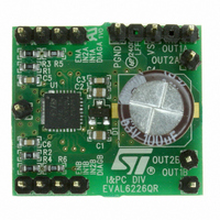
... EVAL6226QR demonstration board using a dual full-bridge L6226Q Introduction This application note describes the demonstration board of the DMOS dual full-bridge L6226Q designed for motor control applications. The board implements a typical application that can be used as a reference design to drive two-phase bipolar stepper motors with currents DC, multiple DC motors and a wide range of inductive loads ...
Page 2
Demonstration board description 1 Demonstration board description Table 1. EVAL6226R pin connections Name VS PGND IN1A IN2A ENA IN1B IN2B ENB DIAGA DIAGB SGND OUT1A OUT2A OUT1B OUT2B 2/8 Type Power supply Bridge A and bridge B power supply Ground ...
Page 3
... The output current detection thresholds are selected by the resistor connected between the IC dedicated pins and ground. Table 2 summarizes the electrical specification of the application and electrical schematic. Table 2. EVAL6226QR electrical specification (recommended value) Supply voltage range (VS) RMS output current rating (OUTx) Switching frequency Input and enable voltage range OCD pins voltage range ...
Page 4
... Demonstration board description Figure 3. EVAL6226QR demonstration board schematic 4/8 AN2758 ...
Page 5
... DISABLE R5 and R6 are used to set the output current detection threshold at about 1.1 A typical Figure 4, Figure 5 value. layout of the two layers of the EVAL6226QR reference design board. A GND area has been used to improve the IC power dissipation. Figure 4. Component placement 24.5 mm Part value 220 nF/25 V ...
Page 6
Demonstration board description Figure 5. Top layer layout Figure 6. Bottom layer layout 6/8 AN2758 ...
Page 7
... AN2758 2 Revision history Table 4. Document revision history Date 06-Oct-2008 28-Jan-2009 Revision 1 Initial release Table 2: EVAL6226QR electrical specification Updated value in 2 (recommended value) on page 3 Revision history Changes 7/8 ...
Page 8
... Information in this document is provided solely in connection with ST products. STMicroelectronics NV and its subsidiaries (“ST”) reserve the right to make changes, corrections, modifications or improvements, to this document, and the products and services described herein at any time, without notice. All ST products are sold pursuant to ST’s terms and conditions of sale. ...