EVAL6206N STMicroelectronics, EVAL6206N Datasheet - Page 29
EVAL6206N
Manufacturer Part Number
EVAL6206N
Description
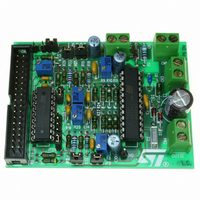
EVAL BOARD FOR L6206N DIP
Manufacturer
STMicroelectronics
Specifications of EVAL6206N
Mfg Application Notes
PractiSPIN AppNote
Design Resources
EVAL6206N/6206N Gerber Files EVAL6206N Schematic/Bill of Materials
Main Purpose
Power Management, H Bridge Driver (Internal FET)
Embedded
No
Utilized Ic / Part
L6205N DIP
Primary Attributes
Dual Full-Bridge (H-Bridge), 2.8A (5.6A Peak). 8 ~ 52 V, 0.3 Ohm
Secondary Attributes
Non-Inverting, Can be Paralleled
Architecture
Analog
Applications
Motor Control
Processor To Be Evaluated
L6206
For Use With
497-4138 - EVALUATION BOARD PRACTISPIN
Lead Free Status / RoHS Status
Lead free / RoHS Compliant
Other names
497-5487


UM0240
Figure 16. The main window
Through the Main Window it is possible to access all software functions. Four different
panels are available:
●
●
●
●
Control Register Panel
Controls present on Control Register Panel allow to modify all the Control Register
Parameters and to write/read the ST7538/ST7540 Control Register.
Transmission Panel
Two method of transmission are available: Sequence and Continuous. With Sequence
method a message can be transmitted across the Mains for n Times, with a delay
between transmissions of 300ms.
Selecting Continuous transmission mode a unique transmission session is performed
and the message to transmit is sent repeatedly across the Mains until the transmission
is interrupted by user or by a Time Out event.
On Industrial Communication Board the transmission session is notified by means of
orange led DL4 that is turned on when the line Rx/Tx is put to "0" logic (i.e. TX session
is on going). When a Time Out Event occurs, the red led DL2 is turned on too.
Receiving Panel
When the device is in Reception mode the green led DL3 of Industrial Communication
Board is turned on.
Two reception methods are available:
–
–
Ping Panel
In order to evaluate the reliability of a communication between two or more devices a
Ping session can be performed. A full variety of statistical data can be collected and an
algorithm of error correction is also included. The ping session consists of a Master that
Reception with synchronization
Due to fact that is not possible to know when the ST7538/ST7540 begins to
demodulate data incoming from the mains, frame synchronization can be required
in order to know when data flow begins. When Frame synchronization is enabled,
the data flow from modem is filtered from the MCU and only when a header is
recognized the data are sent to PC. In this way is assured that, if the transmitted
message is preceded by a preamble (i.e. 0xAAAA o 0x5555) and a header (i.e.
0x9B58), all the following bits are correctly sent to PC. In ST7540 this function can
be performed directly by the modem itself programming the Control register so no
controls are present on the reception window.
Reception without synchronization
With this method, data incoming from the modem are sent directly to the PC.
3
1
2
P RO G RA M SECTIO NS:
1
2
3
M EN U B AR
TO O LB AR
STA TUS BA R
1
Software
29/39
Related parts for EVAL6206N
Image
Part Number
Description
Manufacturer
Datasheet
Request
R

Part Number:
Description:
STMicroelectronics [RIPPLE-CARRY BINARY COUNTER/DIVIDERS]
Manufacturer:
STMicroelectronics
Datasheet:
Part Number:
Description:
STMicroelectronics [LIQUID-CRYSTAL DISPLAY DRIVERS]
Manufacturer:
STMicroelectronics
Datasheet:

Part Number:
Description:
BOARD EVAL FOR MEMS SENSORS
Manufacturer:
STMicroelectronics
Datasheet:
Part Number:
Description:
NPN TRANSISTOR POWER MODULE
Manufacturer:
STMicroelectronics
Datasheet:
Part Number:
Description:
TURBOSWITCH ULTRA-FAST HIGH VOLTAGE DIODE
Manufacturer:
STMicroelectronics
Datasheet:
Part Number:
Description:
Manufacturer:
STMicroelectronics
Datasheet:
Part Number:
Description:
DIODE / SCR MODULE
Manufacturer:
STMicroelectronics
Datasheet:
Part Number:
Description:
DIODE / SCR MODULE
Manufacturer:
STMicroelectronics
Datasheet:
Part Number:
Description:
Search -----> STE16N100
Manufacturer:
STMicroelectronics
Datasheet:
Part Number:
Description:
Search ---> STE53NA50
Manufacturer:
STMicroelectronics
Datasheet:
Part Number:
Description:
NPN Transistor Power Module
Manufacturer:
STMicroelectronics
Datasheet:
Part Number:
Description:
DIODE / SCR MODULE
Manufacturer:
STMicroelectronics
Datasheet: