CDB5378 Cirrus Logic Inc, CDB5378 Datasheet - Page 36
CDB5378
Manufacturer Part Number
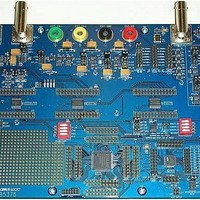
CDB5378
Description
EVALUATION BOARD FOR CS5378
Manufacturer
Cirrus Logic Inc
Datasheets
1.CS5373A-ISZR.pdf
(40 pages)
2.CDB5378.pdf
(16 pages)
3.CDB5378.pdf
(74 pages)
4.CDB5378.pdf
(88 pages)
Specifications of CDB5378
Main Purpose
Seismic Evaluation System
Embedded
Yes, MCU, 8-Bit
Utilized Ic / Part
CS3301A, CS5373A, CS5378
Primary Attributes
Single Digital Filter
Secondary Attributes
Graphical User Interface, SPI™ & USB Interfaces
Processor To Be Evaluated
CS5378
Interface Type
USB
Lead Free Status / RoHS Status
Contains lead / RoHS non-compliant
Lead Free Status / RoHS Status
Lead free / RoHS Compliant, Contains lead / RoHS non-compliant


11. PIN DESCRIPTION
36
Pin
Name
CAP+,
CAP-
BUF+,
BUF-
OUT+,
OUT-
VA+,
VA-
VREF-,
VREF+
INR+,
INF+
INF-,
INR-,
MFLAG
MDATA
MSYNC
MCLK
GND
VD
TDATA
Negative High Precision Output
Negative Analog Power Supply
Positive High Precision Output
Positive Analog Power Supply
Negative Analog Rough Input
Positive Analog Rough Input
Negative Voltage Reference
Negative Analog Fine Input
Positive Voltage Reference
Negative Capacitor Output
Positive Analog Fine Input
Pin # I/O
Positive Capacitor Output
Negative Buffered Output
10
12
13
14
15
16
17
18
19
20
21
11
Positive Buffered Output
1
2
3
4
5
6
7
8
9
O
O
O
O
O
I Voltage reference input. Refer to the Specified Operating Conditions.
I Analog differential rough and fine + inputs. From the + half of the differential anti-alias fil-
I Analog differential rough and fine - inputs. From the - half of the differential anti-alias filter.
I
I Master clock input. CMOS compatible clock input.
I
Capacitor connection for internal anti-alias filter.
Buffered differential analog output.
Precision differential analog output.
Analog power supply. Refer to the Specified Operating Conditions.
ter.
Amplitude overload indicator flag.
Oversampled ΔΣ bit stream conversion output.
Master sync input. Low to high transition resets the internal clock phasing.
System ground.
Digital power supply. Refer to the Specified Operating Conditions.
Test Bit Stream input from digital filter TBS generator.
VREF+
VREF-
CAP+
OUT+
BUF+
CAP-
BUF-
OUT-
INR+
INF+
INR-
INF-
VA+
VA-
1
2
3
4
5
6
7
8
9
10
11
12
13
14
Pin Description
28
27
26
25
24
23
22
21
20
19
18
17
16
15
GND
MODE0
MODE1
MODE2
ATT0
ATT1
ATT2
TDATA
VD
GND
MCLK
MSYNC
MDATA
MFLAG
System Ground
Mode Select
Mode Select
Mode Select
Attenuation Range Select
Attenuation Range Select
Attenuation Range Select
Test Bit Stream Input
Positive Digital Power Supply
System Ground
Master Clock Input
Master Sync Input
Modulator Data Output
Modulator Over-range Indicator
CS5373A
DS703F2
Related parts for CDB5378
Image
Part Number
Description
Manufacturer
Datasheet
Request
R

Part Number:
Description:
Development Kit
Manufacturer:
Cirrus Logic Inc
Datasheet:
Part Number:
Description:
Development Kit
Manufacturer:
Cirrus Logic Inc
Datasheet:


Part Number:
Description:
High-efficiency PFC + Fluorescent Lamp Driver Reference Design
Manufacturer:
Cirrus Logic Inc
Datasheet:
Part Number:
Description:
Development Kit
Manufacturer:
Cirrus Logic Inc
Datasheet:
Part Number:
Description:
Development Kit
Manufacturer:
Cirrus Logic Inc
Datasheet:

Part Number:
Description:
Development Kit
Manufacturer:
Cirrus Logic Inc
Datasheet:
Part Number:
Description:
Development Kit
Manufacturer:
Cirrus Logic Inc
Datasheet:
Part Number:
Description:
Development Kit
Manufacturer:
Cirrus Logic Inc
Datasheet:
Part Number:
Description:
Development Kit
Manufacturer:
Cirrus Logic Inc
Datasheet:

Part Number:
Description:
EVALUATION BOARD FOR CS8427
Manufacturer:
Cirrus Logic Inc
Datasheet:

Part Number:
Description:
BOARD EVAL FOR CS8416 RCVR
Manufacturer:
Cirrus Logic Inc
Datasheet:

Part Number:
Description:
EVALUATION BOARD FOR CS8420
Manufacturer:
Cirrus Logic Inc
Datasheet:

Part Number:
Description:
KIT DEVELOPMENT EP9315 ARM9
Manufacturer:
Cirrus Logic Inc
Datasheet:

Part Number:
Description:
KIT DEVELOPMENT EP9302 ARM9
Manufacturer:
Cirrus Logic Inc
Datasheet: