CDB5378 Cirrus Logic Inc, CDB5378 Datasheet - Page 25
CDB5378
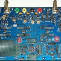
Manufacturer Part Number
CDB5378
Description
EVALUATION BOARD FOR CS5378
Manufacturer
Cirrus Logic Inc
Datasheets
1.CS5373A-ISZR.pdf
(40 pages)
2.CDB5378.pdf
(16 pages)
3.CDB5378.pdf
(74 pages)
4.CDB5378.pdf
(88 pages)
Specifications of CDB5378
Main Purpose
Seismic Evaluation System
Embedded
Yes, MCU, 8-Bit
Utilized Ic / Part
CS3301A, CS5373A, CS5378
Primary Attributes
Single Digital Filter
Secondary Attributes
Graphical User Interface, SPI™ & USB Interfaces
Processor To Be Evaluated
CS5378
Interface Type
USB
Lead Free Status / RoHS Status
Contains lead / RoHS non-compliant
Lead Free Status / RoHS Status
Lead free / RoHS Compliant, Contains lead / RoHS non-compliant


calibration and differential pulse tests. In mode
4, both sets of analog outputs (OUT and BUF)
are enabled.
5.3.2
The second DC test mode (MODE 5) enables
the modulator and DC test circuitry to create a
precision differential DC analog output voltage
as the final measurement for gain calibration
and as the step/pulse output for differential
pulse tests. In mode 5, both sets of analog out-
puts (OUT and BUF) are enabled.
In DC differential mode (MODE 5) the level-
shifting buffer circuitry adds low-level 32 kHz
switched-capacitor noise to the DC output.
This noise is out of the measurement band-
width
CS3301A/02A amplifier and CS5373A modu-
lator and is rejected by the CS5378 digital fil-
ter. This 32 kHz switched-capacitor noise
does not affect DC system tests, though it may
be visible on an oscilloscope at high gain lev-
els.
By
DS703F2
CS5373A
CS5373A
MODE 4
MODE 5
measuring
for
DC Differential
OUT+
OUT+
BUF+
BUF+
OUT-
OUT-
BUF-
BUF-
Figure 12. DC Test Modes
systems
both
designed
DC
test
Differential
Differential
Maximum
Maximum
-0.15 V
Common
-0.15 V
Common
2.5 V
2.5 V
Approx
Approx
Mode
Mode
with
modes
DC
DC
DC
DC
a
(MODE 4, 5), precision gain-calibration coeffi-
cients can be calculated for the measurement
channel. By first measuring the differential off-
set of the DC common mode output (MODE 4)
and then measuring the DC differential mode
amplitude (MODE 5), a precise offset-correct-
ed, volts-to-codes conversion ratio can be cal-
culated. This known ratio is then used along
with the CS5378 digital filter GAIN register to
normalize the full-scale amplitude to match
other channels in the measurement network.
By switching between DC common mode
(MODE 4)
(MODE 5), pulse waveforms can be created to
characterize the step response of the mea-
surement channel. If a pulse test requires pre-
cise timing control, an external controller
should directly toggle the MODE pins of the
CS5373A to avoid delays associated with writ-
ing to the CS5378 digital filter GPIO register.
Sensor impedance can be measured using
DC differential mode (MODE 5), provided
matched series resistors are installed between
the BUF analog outputs and the sensor. Ap-
plying the known DC differential voltage to the
resistor-sensor-resistor string permits a ratio-
metric sensor impedance calculation from the
measured voltage drop across the sensor.
Switching
(MODE 5) and modulator mode (MODE 0) can,
in the case of a moving-coil geophone, test basic
parameters of the electro-mechanical transfer
function. The voltage relaxation characteristic of
the sensor when switching the analog outputs
from a differential DC voltage to high impedance
depends primarily on the geophone resonant
frequency and damping factor.
5.4 Sleep Mode
Sleep mode (MODE 7) saves system power
when measurements are not required by turning
off the modulator, AC test circuitry, and DC test
circuitry. In sleep mode the modulator digital out-
puts and the BUF and OUT analog outputs are
high impedance.
between
and
DC
DC
differential
differential
CS5373A
mode
mode
25
Related parts for CDB5378
Image
Part Number
Description
Manufacturer
Datasheet
Request
R

Part Number:
Description:
Development Kit
Manufacturer:
Cirrus Logic Inc
Datasheet:
Part Number:
Description:
Development Kit
Manufacturer:
Cirrus Logic Inc
Datasheet:


Part Number:
Description:
High-efficiency PFC + Fluorescent Lamp Driver Reference Design
Manufacturer:
Cirrus Logic Inc
Datasheet:
Part Number:
Description:
Development Kit
Manufacturer:
Cirrus Logic Inc
Datasheet:
Part Number:
Description:
Development Kit
Manufacturer:
Cirrus Logic Inc
Datasheet:

Part Number:
Description:
Development Kit
Manufacturer:
Cirrus Logic Inc
Datasheet:
Part Number:
Description:
Development Kit
Manufacturer:
Cirrus Logic Inc
Datasheet:
Part Number:
Description:
Development Kit
Manufacturer:
Cirrus Logic Inc
Datasheet:
Part Number:
Description:
Development Kit
Manufacturer:
Cirrus Logic Inc
Datasheet:

Part Number:
Description:
EVALUATION BOARD FOR CS8427
Manufacturer:
Cirrus Logic Inc
Datasheet:

Part Number:
Description:
BOARD EVAL FOR CS8416 RCVR
Manufacturer:
Cirrus Logic Inc
Datasheet:

Part Number:
Description:
EVALUATION BOARD FOR CS8420
Manufacturer:
Cirrus Logic Inc
Datasheet:

Part Number:
Description:
KIT DEVELOPMENT EP9315 ARM9
Manufacturer:
Cirrus Logic Inc
Datasheet:

Part Number:
Description:
KIT DEVELOPMENT EP9302 ARM9
Manufacturer:
Cirrus Logic Inc
Datasheet: