CDB5378 Cirrus Logic Inc, CDB5378 Datasheet - Page 24
CDB5378
Manufacturer Part Number
CDB5378
Description
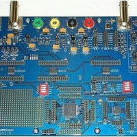
EVALUATION BOARD FOR CS5378
Manufacturer
Cirrus Logic Inc
Datasheets
1.CS5373A-ISZR.pdf
(40 pages)
2.CDB5378.pdf
(16 pages)
3.CDB5378.pdf
(74 pages)
4.CDB5378.pdf
(88 pages)
Specifications of CDB5378
Main Purpose
Seismic Evaluation System
Embedded
Yes, MCU, 8-Bit
Utilized Ic / Part
CS3301A, CS5373A, CS5378
Primary Attributes
Single Digital Filter
Secondary Attributes
Graphical User Interface, SPI™ & USB Interfaces
Processor To Be Evaluated
CS5378
Interface Type
USB
Lead Free Status / RoHS Status
Contains lead / RoHS non-compliant
Lead Free Status / RoHS Status
Lead free / RoHS Compliant, Contains lead / RoHS non-compliant


Differential AC test signals out of the CS5373A
consist of two halves with equal but opposite
magnitude, varying about a common mode
voltage. A full-scale 5 V
nal centered on a -0.15 V common mode volt-
age will have:
For the opposite case:
So the total swing for SIG+ relative to SIG- is
(+2.5 V) - (-2.5 V) = 5 V
calculation can be done for SIG- relative to
SIG+. It’s important to note that a 5 V
ential signal centered on a -0.15 V common
mode voltage never exceeds +1.1 V with re-
spect to ground and never drops below -1.4 V
with respect to ground on either half. By defini-
tion, differential voltages are measured with
respect to the opposite half, not relative to
ground. A voltmeter differentially measuring
between SIG+ and SIG- in the above example
would correctly read 1.767 V
5.2.2
The final AC test mode (MODE 6) enables the
modulator and AC test circuitry to create a
matched AC common mode analog signal for
CMRR testing of the measurement channel. In
24
SIG+ = -0.15 V + 1.25 V = +1.1 V
SIG- = -0.15 V - 1.25 V = -1.4 V
SIG+ is +2.5 V relative to SIG-
SIG+ = -0.15 V - 1.25 V = -1.4 V
SIG- = -0.15 V + 1.25 V = +1.1 V
SIG+ is -2.5 V relative to SIG-
CS5373A
MODE 6
AC Common Mode
Figure 11. AC Common Mode
OUT+
BUF+
OUT-
BUF-
pp
PP
differential. A similar
differential AC sig-
rms
, or 5 V
Maximum
Maximum
Common
Common
2.5 Vpp
2.5 Vpp
pp
Mode
Mode
pp
differ-
.
mode 6, both sets of analog outputs (OUT and
BUF) are enabled. There is no AC common
mode output for an attenuator setting of 1/64.
Gross leakage in the sensor channel can be
detected by applying a full-scale AC common
mode signal. If there is a significant differential
mismatch in the channel due to sensor leak-
age, the AC common mode signal will be con-
verted to a measurable differential signal at
the fundamental frequency.
5.2.3
For the CS5373A’s low-power ΔΣ DAC archi-
tecture to remain stable, the TDATA input bit
stream should only encode 100 Hz or lower
bandwidth analog signals. For TDATA bit
stream frequencies above 100 Hz (for exam-
ple, TBS impulse mode), the encoded ampli-
tude must be reduced -20 dB below full scale
to guarantee stability.
If the CS5373A’s low-power ΔΣ DAC architec-
ture becomes unstable, persistent elevated
noise will be present on the analog outputs
and AC linearity will be poor. To recover stabil-
ity, place the CS5373A into power down or
sleep mode and restart the CS5378 test bit
stream generator before placing the CS5373A
back into an AC test mode.
5.3 DC Test Modes
DC test modes enable the modulator and DC
test circuitry to create precision level-shifted
and buffered versions of the voltage reference
input as precision DC common mode and DC
differential analog outputs. The absolute accu-
racy of the DC test modes is highly dependent
on the absolute accuracy of the voltage refer-
ence input voltage.
5.3.1
The first DC test mode (MODE 4) enables the
modulator and DC test circuitry to create a
matched DC common mode analog output
voltage as a baseline measurement for gain
DAC Stability
DC Common Mode
CS5373A
DS703F2
Related parts for CDB5378
Image
Part Number
Description
Manufacturer
Datasheet
Request
R

Part Number:
Description:
Development Kit
Manufacturer:
Cirrus Logic Inc
Datasheet:
Part Number:
Description:
Development Kit
Manufacturer:
Cirrus Logic Inc
Datasheet:


Part Number:
Description:
High-efficiency PFC + Fluorescent Lamp Driver Reference Design
Manufacturer:
Cirrus Logic Inc
Datasheet:
Part Number:
Description:
Development Kit
Manufacturer:
Cirrus Logic Inc
Datasheet:
Part Number:
Description:
Development Kit
Manufacturer:
Cirrus Logic Inc
Datasheet:

Part Number:
Description:
Development Kit
Manufacturer:
Cirrus Logic Inc
Datasheet:
Part Number:
Description:
Development Kit
Manufacturer:
Cirrus Logic Inc
Datasheet:
Part Number:
Description:
Development Kit
Manufacturer:
Cirrus Logic Inc
Datasheet:
Part Number:
Description:
Development Kit
Manufacturer:
Cirrus Logic Inc
Datasheet:

Part Number:
Description:
EVALUATION BOARD FOR CS8427
Manufacturer:
Cirrus Logic Inc
Datasheet:

Part Number:
Description:
BOARD EVAL FOR CS8416 RCVR
Manufacturer:
Cirrus Logic Inc
Datasheet:

Part Number:
Description:
EVALUATION BOARD FOR CS8420
Manufacturer:
Cirrus Logic Inc
Datasheet:

Part Number:
Description:
KIT DEVELOPMENT EP9315 ARM9
Manufacturer:
Cirrus Logic Inc
Datasheet:

Part Number:
Description:
KIT DEVELOPMENT EP9302 ARM9
Manufacturer:
Cirrus Logic Inc
Datasheet: