CDB5378 Cirrus Logic Inc, CDB5378 Datasheet - Page 30
CDB5378
Manufacturer Part Number
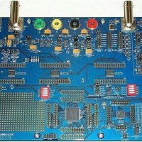
CDB5378
Description
EVALUATION BOARD FOR CS5378
Manufacturer
Cirrus Logic Inc
Datasheets
1.CS5373A-ISZR.pdf
(40 pages)
2.CDB5378.pdf
(16 pages)
3.CDB5378.pdf
(74 pages)
4.CDB5378.pdf
(88 pages)
Specifications of CDB5378
Main Purpose
Seismic Evaluation System
Embedded
Yes, MCU, 8-Bit
Utilized Ic / Part
CS3301A, CS5373A, CS5378
Primary Attributes
Single Digital Filter
Secondary Attributes
Graphical User Interface, SPI™ & USB Interfaces
Processor To Be Evaluated
CS5378
Interface Type
USB
Lead Free Status / RoHS Status
Contains lead / RoHS non-compliant
Lead Free Status / RoHS Status
Lead free / RoHS Compliant, Contains lead / RoHS non-compliant


tests and two external differential inputs. One
external input is typically dedicated to sensor
measurements and the other to testing the
electronics channel.
The OUT± outputs are enabled in all opera-
tional
(MODE 0), “AC BUF Only” mode (MODE 3)
and sleep mode (MODE 7). In modulator
mode, AC BUF Only mode and sleep mode
the OUT± pins are high impedance.
7.4 DAC BUF± Buffered Output
The test DAC BUF± pins are buffered differen-
tial analog outputs for testing external sensors
such as geophones or hydrophones. The buff-
ered outputs have reduced performance spec-
ifications compared with the OUT± outputs,
but are less sensitive to external loading.
The BUF± outputs are enabled in all operation-
al modes except modulator mode (MODE 0),
“AC OUT Only” mode (MODE 2) and sleep
mode
AC OUT only and sleep mode the BUF± pins
are high impedance to ensure they do not in-
terfere with sensor operation during normal
data acquisition.
For sensor impedance testing, it is required to
place matched series resistors in between the
BUF± outputs and the differential sensor. With
known series resistors and a known DC differ-
ential source voltage, sensor resistance can
be calculated ratiometrically from the mea-
sured voltage drop across the sensor.
7.5 DAC CAP± Connection
The CS5373A test DAC requires a 10 nF C0G
type capacitor to be connected differentially
across the CAP± pins. This capacitor creates
an internal anti-alias filter to eliminate high-fre-
30
modes
(MODE 7).
except
In
modulator
modulator
mode,
mode
quency signals from the OUT± and BUF± ana-
log outputs and helps to maintain the stability
of the low-power ΔΣ DAC circuitry.
A COG, NPO or similar high-quality capacitor
is required for CAP
types, such as X7R, do not have the required
linearity. Using a poor-quality capacitor on
CAP± will significantly degrade THD perfor-
mance of the test DAC AC operational modes.
7.6 Analog Differential Signals
Differential AC test signals into and out of the
CS5373A consist of two halves with equal but
opposite magnitude varying about a common
mode voltage. A full-scale 5 V
AC signal centered on a -0.15 V common
mode voltage will have:
For the opposite case:
So the total swing for SIG+ relative to SIG- is
(+2.5 V) - (-2.5 V) = 5 V
calculation can be done for SIG- relative to
SIG+. It’s important to note that a 5 V
ential signal centered on a -0.15 V common
mode voltage never exceeds +1.1 V with re-
spect to ground and never drops below -1.4 V
with respect to ground on either half. By defini-
tion, differential voltages are measured with
respect to the opposite half, not relative to
ground. A voltmeter differentially measuring
between SIG+ and SIG- in the above example
would correctly read 1.767 V
SIG+ = -0.15 V + 1.25 V = +1.1 V
SIG- = -0.15 V - 1.25 V = -1.4 V
SIG+ is +2.5 V relative to SIG-
SIG+ = -0.15 V - 1.25 V = -1.4 V
SIG- = -0.15 V + 1.25 V = +1.1 V
SIG+ is -2.5 V relative to SIG-
±
pp
since other capacitor
differential. A similar
rms
, or 5 V
PP
CS5373A
differential
pp
DS703F2
pp
differ-
.
Related parts for CDB5378
Image
Part Number
Description
Manufacturer
Datasheet
Request
R

Part Number:
Description:
Development Kit
Manufacturer:
Cirrus Logic Inc
Datasheet:
Part Number:
Description:
Development Kit
Manufacturer:
Cirrus Logic Inc
Datasheet:


Part Number:
Description:
High-efficiency PFC + Fluorescent Lamp Driver Reference Design
Manufacturer:
Cirrus Logic Inc
Datasheet:
Part Number:
Description:
Development Kit
Manufacturer:
Cirrus Logic Inc
Datasheet:
Part Number:
Description:
Development Kit
Manufacturer:
Cirrus Logic Inc
Datasheet:

Part Number:
Description:
Development Kit
Manufacturer:
Cirrus Logic Inc
Datasheet:
Part Number:
Description:
Development Kit
Manufacturer:
Cirrus Logic Inc
Datasheet:
Part Number:
Description:
Development Kit
Manufacturer:
Cirrus Logic Inc
Datasheet:
Part Number:
Description:
Development Kit
Manufacturer:
Cirrus Logic Inc
Datasheet:

Part Number:
Description:
EVALUATION BOARD FOR CS8427
Manufacturer:
Cirrus Logic Inc
Datasheet:

Part Number:
Description:
BOARD EVAL FOR CS8416 RCVR
Manufacturer:
Cirrus Logic Inc
Datasheet:

Part Number:
Description:
EVALUATION BOARD FOR CS8420
Manufacturer:
Cirrus Logic Inc
Datasheet:

Part Number:
Description:
KIT DEVELOPMENT EP9315 ARM9
Manufacturer:
Cirrus Logic Inc
Datasheet:

Part Number:
Description:
KIT DEVELOPMENT EP9302 ARM9
Manufacturer:
Cirrus Logic Inc
Datasheet: