CDB42448 Cirrus Logic Inc, CDB42448 Datasheet - Page 54
CDB42448
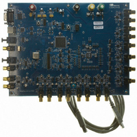
Manufacturer Part Number
CDB42448
Description
BOARD EVAL FOR CS42448 CODEC
Manufacturer
Cirrus Logic Inc
Specifications of CDB42448
Main Purpose
Audio, CODEC
Embedded
Yes, FPGA / CPLD
Utilized Ic / Part
CS42448
Primary Attributes
24-Bit, 192 kHz, 6 ADCs: 102dB Dynamic Range, 8 DACs: 105dB Dynamic Range
Secondary Attributes
Time Division Multiplexed (TDM), I2C, and SPI Interface, Popguard® Technology
Description/function
Audio CODECs
Operating Supply Voltage
5 V to 12 V
Product
Audio Modules
For Use With/related Products
CS42448
Lead Free Status / RoHS Status
Contains lead / RoHS non-compliant
Lead Free Status / RoHS Status
Lead free / RoHS Compliant, Contains lead / RoHS non-compliant
Other names
598-1151


54
7.1.1
7.1.2
Passive Input Filter
The passive filter implementation shown in
will not provide optimum source impedance for the ADC modulators. Full analog performance will there-
fore not be realized using a passive filter.
In this topology the distortion performance is affected, but the dynamic range performance is not limited.
Passive Input Filter w/Attenuation
Some applications may require signal attenuation prior to the ADC. The full-scale input voltage will scale
with the analog power supply voltage. For VA = 5.0 V, the full-scale input voltage is approximately
2.8 Vpp, or 1 Vrms (most consumer audio line-level outputs range from 1.5 to 2 Vrms).
Figure 29
pedance on the analog inputs, the full distortion performance cannot be realized. Also, the resistor divider
circuit will determine the input impedance into the input filter. In the circuit shown in
impedance is approximately 5 kΩ. By doubling the resistor values, the input impedance will increase to
10 kΩ. However, in this case the distortion performance will drop due to the increase in series resistance
on the analog inputs.
shows a passive input filter with 6 dB of signal attenuation. Due to the relatively high input im-
100 kΩ
100 kΩ
100 kΩ
Figure 28. Passive Input Filter
150 Ω
150 Ω
150 Ω
10 μF
10 μF
10 μF
Figure 28
Figure 28
4.7 μF
illustrates the unity gain, passive input filter solution.
2700 pF
2700 pF
2700 pF
C0G
C0G
C0G
will attenuate any noise energy at 6.144 MHz but
AIN1+,2+,3+,4+
AIN1-,2-,3-,4-
AIN5A,6A
AIN5B,6B
ADC1-2
ADC3
Figure
CS42448
29, the input
DS648F3
Related parts for CDB42448
Image
Part Number
Description
Manufacturer
Datasheet
Request
R

Part Number:
Description:
Development Kit
Manufacturer:
Cirrus Logic Inc
Datasheet:
Part Number:
Description:
Development Kit
Manufacturer:
Cirrus Logic Inc
Datasheet:


Part Number:
Description:
High-efficiency PFC + Fluorescent Lamp Driver Reference Design
Manufacturer:
Cirrus Logic Inc
Datasheet:
Part Number:
Description:
Development Kit
Manufacturer:
Cirrus Logic Inc
Datasheet:
Part Number:
Description:
Development Kit
Manufacturer:
Cirrus Logic Inc
Datasheet:

Part Number:
Description:
Development Kit
Manufacturer:
Cirrus Logic Inc
Datasheet:
Part Number:
Description:
Development Kit
Manufacturer:
Cirrus Logic Inc
Datasheet:
Part Number:
Description:
Development Kit
Manufacturer:
Cirrus Logic Inc
Datasheet:
Part Number:
Description:
Development Kit
Manufacturer:
Cirrus Logic Inc
Datasheet:

Part Number:
Description:
EVALUATION BOARD FOR CS8427
Manufacturer:
Cirrus Logic Inc
Datasheet:

Part Number:
Description:
BOARD EVAL FOR CS8416 RCVR
Manufacturer:
Cirrus Logic Inc
Datasheet:

Part Number:
Description:
EVALUATION BOARD FOR CS8420
Manufacturer:
Cirrus Logic Inc
Datasheet:

Part Number:
Description:
KIT DEVELOPMENT EP9315 ARM9
Manufacturer:
Cirrus Logic Inc
Datasheet:

Part Number:
Description:
KIT DEVELOPMENT EP9302 ARM9
Manufacturer:
Cirrus Logic Inc
Datasheet: