CDB42448 Cirrus Logic Inc, CDB42448 Datasheet - Page 44
CDB42448
Manufacturer Part Number
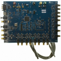
CDB42448
Description
BOARD EVAL FOR CS42448 CODEC
Manufacturer
Cirrus Logic Inc
Specifications of CDB42448
Main Purpose
Audio, CODEC
Embedded
Yes, FPGA / CPLD
Utilized Ic / Part
CS42448
Primary Attributes
24-Bit, 192 kHz, 6 ADCs: 102dB Dynamic Range, 8 DACs: 105dB Dynamic Range
Secondary Attributes
Time Division Multiplexed (TDM), I2C, and SPI Interface, Popguard® Technology
Description/function
Audio CODECs
Operating Supply Voltage
5 V to 12 V
Product
Audio Modules
For Use With/related Products
CS42448
Lead Free Status / RoHS Status
Contains lead / RoHS non-compliant
Lead Free Status / RoHS Status
Lead free / RoHS Compliant, Contains lead / RoHS non-compliant
Other names
598-1151


44
6.5
6.5.1
6.5.2
6.5.3
FREEZE
7
Interface Formats (Address 04h)
Freeze Controls (FREEZE)
Default = 0
Function:
This function will freeze the previous settings of, and allow modifications to be made to the channel mutes,
the DAC and ADC Volume Control/Channel Invert registers without the changes taking effect until the
FREEZE is disabled. To have multiple changes in these control port registers take effect simultaneously,
enable the FREEZE bit, make all register changes, then disable the FREEZE bit.
Auxiliary Digital Interface Format (AUX_DIF)
Default = 0
0 - Left Justified
1 - I²S
Function:
This bit selects the digital interface format used for the AUX Serial Port. The required relationship between
the Left/Right clock, serial clock and serial data is defined by the Digital Interface Format and the options
are detailed in
DAC Digital Interface Format (DAC_DIF[2:0])
Default = 110
Function:
These bits select the digital interface format used for the DAC Serial Port. The required relationship between
the Left/Right clock, serial clock and serial data is defined by the Digital Interface Format; the options are
detailed in the section
Refer to
DAC_DIF2
MFreq2
0
0
0
0
1
0
0
0
AUX_DIF
Table 9, “Serial Audio Interface Channel Allocations,” on page
6
MFreq1
DAC_DIF1
Table 11. MCLK Frequency Settings for TDM & OLM Interface Formats
Figures
0
0
1
1
X
0
0
1
DAC_DIF2
“CODEC Digital Interface Formats” on page
23-24.
5
MFreq0
DAC_DIF0
X
0
1
0
1
Table 12. DAC Digital Interface Formats
0
1
0
DAC_DIF1
1.0290 MHz to 12.8000 MHz
1.5360 MHz to 19.2000 MHz
2.0480 MHz to 25.6000 MHz
3.0720 MHz to 38.4000 MHz
4.0960 MHz to 51.2000 MHz
4
Left Justified, up to 24-bit data
I²S, up to 24-bit data
Right Justified, 24-bit data
Description
DAC_DIF0
Description
3
ADC_DIF2
31.
2
34.
SSM
1024
256
384
512
768
ADC_DIF1
Format
Ratio (xFs)
1
0
1
2
DSM
N/A
N/A
256
384
512
CS42448
ADC_DIF0
Figure 16
Figure 15
Figure 17
Figure
DS648F3
QSM
N/A
N/A
N/A
N/A
256
0
Related parts for CDB42448
Image
Part Number
Description
Manufacturer
Datasheet
Request
R

Part Number:
Description:
Development Kit
Manufacturer:
Cirrus Logic Inc
Datasheet:
Part Number:
Description:
Development Kit
Manufacturer:
Cirrus Logic Inc
Datasheet:


Part Number:
Description:
High-efficiency PFC + Fluorescent Lamp Driver Reference Design
Manufacturer:
Cirrus Logic Inc
Datasheet:
Part Number:
Description:
Development Kit
Manufacturer:
Cirrus Logic Inc
Datasheet:
Part Number:
Description:
Development Kit
Manufacturer:
Cirrus Logic Inc
Datasheet:

Part Number:
Description:
Development Kit
Manufacturer:
Cirrus Logic Inc
Datasheet:
Part Number:
Description:
Development Kit
Manufacturer:
Cirrus Logic Inc
Datasheet:
Part Number:
Description:
Development Kit
Manufacturer:
Cirrus Logic Inc
Datasheet:
Part Number:
Description:
Development Kit
Manufacturer:
Cirrus Logic Inc
Datasheet:

Part Number:
Description:
EVALUATION BOARD FOR CS8427
Manufacturer:
Cirrus Logic Inc
Datasheet:

Part Number:
Description:
BOARD EVAL FOR CS8416 RCVR
Manufacturer:
Cirrus Logic Inc
Datasheet:

Part Number:
Description:
EVALUATION BOARD FOR CS8420
Manufacturer:
Cirrus Logic Inc
Datasheet:

Part Number:
Description:
KIT DEVELOPMENT EP9315 ARM9
Manufacturer:
Cirrus Logic Inc
Datasheet:

Part Number:
Description:
KIT DEVELOPMENT EP9302 ARM9
Manufacturer:
Cirrus Logic Inc
Datasheet: