CDB4265 Cirrus Logic Inc, CDB4265 Datasheet - Page 9
CDB4265
Manufacturer Part Number
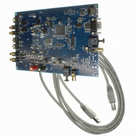
CDB4265
Description
BOARD EVAL FOR CS4265 CODEC
Manufacturer
Cirrus Logic Inc
Specifications of CDB4265
Main Purpose
Audio, CODEC
Embedded
No
Utilized Ic / Part
CS4265
Primary Attributes
Stereo, 24-Bit, 192 kHz Sample Rate
Secondary Attributes
Graphic User Interface, S/PDIF/ I2S / I2C / SPI Interface
Description/function
Audio CODECs
Operating Supply Voltage
5 V
Product
Audio Modules
For Use With/related Products
CS4265
Lead Free Status / RoHS Status
Contains lead / RoHS non-compliant
Lead Free Status / RoHS Status
Lead free / RoHS Compliant, Contains lead / RoHS non-compliant
Other names
598-1001


3.3
3.4
DS657DB1
Register Maps Tab
The Register Maps tab provides low level control over the register level settings of the CS4265, CS8416,
and FPGA. Each device is displayed on a separate tab. Register values can be modified bit-wise or byte-
wise. For bit-wise, click the appropriate push button for the desired bit. For byte-wise, the desired hex value
can be typed directly in the register address box in the register map.
Pre-Configured Script Files
Pre-configured script files are provided with the CDB4265 to allow easy initial board bring-up. The board
configurations stored within these files are described in sections 3.4.1 - 3.4.2.
3.4.1
Using the pre-configured script file named “Oscillator Clock - Line In to DAC & SPDIF Out.txt”, an analog
input signal applied to the line level inputs of the CS4265 input multiplexer will be digitized by the ADC, trans-
mitted in S/PDIF format by the CS4265 internal S/PDIF transmitter, and converted to analog by the DAC
and output through the passive output filter.
The canned oscillator is the source of MCLK. The CS4265 is the sub-clock master to the PCM I/O header.
Oscillator Clock - Line In to DAC & SPDIF Out
Figure 3. Register Maps Tab
CDB4265
9
Related parts for CDB4265
Image
Part Number
Description
Manufacturer
Datasheet
Request
R

Part Number:
Description:
Development Kit
Manufacturer:
Cirrus Logic Inc
Datasheet:
Part Number:
Description:
Development Kit
Manufacturer:
Cirrus Logic Inc
Datasheet:


Part Number:
Description:
High-efficiency PFC + Fluorescent Lamp Driver Reference Design
Manufacturer:
Cirrus Logic Inc
Datasheet:
Part Number:
Description:
Development Kit
Manufacturer:
Cirrus Logic Inc
Datasheet:
Part Number:
Description:
Development Kit
Manufacturer:
Cirrus Logic Inc
Datasheet:

Part Number:
Description:
Development Kit
Manufacturer:
Cirrus Logic Inc
Datasheet:
Part Number:
Description:
Development Kit
Manufacturer:
Cirrus Logic Inc
Datasheet:
Part Number:
Description:
Development Kit
Manufacturer:
Cirrus Logic Inc
Datasheet:
Part Number:
Description:
Development Kit
Manufacturer:
Cirrus Logic Inc
Datasheet:

Part Number:
Description:
EVALUATION BOARD FOR CS8427
Manufacturer:
Cirrus Logic Inc
Datasheet:

Part Number:
Description:
BOARD EVAL FOR CS8416 RCVR
Manufacturer:
Cirrus Logic Inc
Datasheet:

Part Number:
Description:
EVALUATION BOARD FOR CS8420
Manufacturer:
Cirrus Logic Inc
Datasheet:

Part Number:
Description:
KIT DEVELOPMENT EP9315 ARM9
Manufacturer:
Cirrus Logic Inc
Datasheet:

Part Number:
Description:
KIT DEVELOPMENT EP9302 ARM9
Manufacturer:
Cirrus Logic Inc
Datasheet: