V2DIP1-48 FTDI, Future Technology Devices International Ltd, V2DIP1-48 Datasheet - Page 7
V2DIP1-48
Manufacturer Part Number
V2DIP1-48
Description
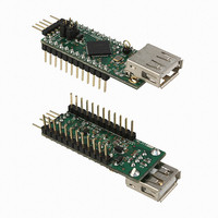
MOD MCU-USB HOST CTLR 24-DIP
Manufacturer
FTDI, Future Technology Devices International Ltd
Series
Vinculum-IIr
Datasheet
1.V2DIP1-48.pdf
(25 pages)
Specifications of V2DIP1-48
Main Purpose
Interface, USB 2.0 Host/Controller
Embedded
Yes, ASIC
Utilized Ic / Part
VNC2-48Q
Primary Attributes
Single A-Type Connector, UART / Parallel FIFO / SPI Interfaces
Secondary Attributes
Second USB Port is Available via Pins, Traffic LEDs
Lead Free Status / RoHS Status
Lead free / RoHS Compliant
Other names
768-1057


3.2 Pin Signal Description
Table 3.1 - Pin Signal Descriptions
(VDIP1)
Pin No.
(11)
(12)
(23)
(22)
J1-10
J1-11
J1-12
(10)
(24)
J1-1
(1)
J1-2
(2)
J1-3
J1-4
(4)
J1-5
(5)
J1-6
(6)
J1-7
(7)
J1-8
(9)
J2-1
J2-3
J2-4
(21)
J1-9
J2-2
(8)
(3)
IOBUS25
(VDIP1)
IOBUS12
IOBUS13
IOBUS14
IOBUS15
IOBUS16
IOBUS17
USBD1M
USBD1P
RESET#
IOBUS5
IOBUS6
PROG#
Name
GND
5V0
3V3
on PCB
Name
PROG#
U1M
Copyright © 2010 Future Technology Devices International Limited
IO13
IO14
IO15
IO16
IO17
RST#
IO25
Pin
GND
IO12
5V0
U1P
3V3
IO5
IO6
`
PWR Input 5.0V module supply pin. This pin can be used to provide the 5.0V
Output
Output
Type
Input
Input
PWR
PWR
I/O
I/O
I/O
I/O
I/O
I/O
I/O
I/O
I/O
USB host / slave port 1 - USB Data Signal Plus with integrated pull up /
pull down resistor. Module has on board 27 Ω USB series resistor. This
pin can be brought out along with pin 5 to provide a second USB port, if
required
USB host / slave port 1 - USB Data Signal Minus with integrated pull up
/ pull down resistor. Module has on board 27 Ω USB series resistor. This
pin can be brought out along with pin 4 to provide a second USB port, if
required
V2DIP1-48 VNC2-48 Development Module Datasheet Version 1.01
input to the V2DIP1-48 when the V2DIP1-48 is not powered from the
USB connector (VBUS) or the debugger interface. Also connected to
DIL connector pins J1-2, J1-3 and J1-9 and J3-6.
USB port 1 traffic activity indicator LED. This pin is hard wired to a
green LED on boardthe PCB. It is also brought out onto this pin which
allows for the possibility of bringing an additional LED traffic indicator
out of the V2DIP1 board. For example, if the V2DIP1 USB connector is
brought out onto an instrument front panel, an activity LED could be
mounted along side it.
USB port 2 traffic activity indicator LED. This pin is hard wired to a
green LED on board the PCB. It is also brought out onto this pin which
allows for the possibility of bringing an additional LED traffic indicator
out of the V2DIP1 board. For example, if the V2DIP1 USB connector is
brought out onto an instrument front panel, an activity LED could be
mounted along side it.
5V safe bidirectional data / control bus bit 12
Module ground supply pin
5V safe bidirectional data / control bus bit 13
5V safe bidirectional data / control bus bit 14
5V safe bidirectional data / control bus bit 15
5V safe bidirectional data / control bus bit 16
5V safe bidirectional data / control bus bit 17
3.3V output from V2DIP1’s on board 3.3V L.D.O.
This pin is used in combination with the RESET# pin and the UART /
parallel FIFO / SPI interface to program firmware into the VNCL2.
Can be used by an external device to reset the VNCL2. This pin can be
used in combination with PROG# and the UART / parallel FIFO / SPI
interface to program firmware into the VNCL2.
5V safe bidirectional data / control bus bit 25
Description
Document Reference No.: FT_000236
Clearance No.: FTDI# 153
6
Related parts for V2DIP1-48
Image
Part Number
Description
Manufacturer
Datasheet
Request
R

Part Number:
Description:
MOD MCU-USB HOST CTLR 24-DIP
Manufacturer:
FTDI, Future Technology Devices International Ltd
Datasheet:

Part Number:
Description:
MOD MCU-USB HOST CTLR 60-DIP
Manufacturer:
FTDI, Future Technology Devices International Ltd
Datasheet:

Part Number:
Description:
IC USB TO SERIAL UART 32-QFN
Manufacturer:
FTDI, Future Technology Devices International Ltd

Part Number:
Description:
IC USB HOST CTLR VINCULUM 48LQFP
Manufacturer:
FTDI, Future Technology Devices International Ltd
Datasheet:

Part Number:
Description:
IC USB HOST VINCULUM-II 32QFN
Manufacturer:
FTDI, Future Technology Devices International Ltd
Datasheet:
Part Number:
Description:
IC USB HOST VINCULUM-II 32LQFN
Manufacturer:
FTDI, Future Technology Devices International Ltd
Datasheet:
Part Number:
Description:
IC USB HOST VINCULUM-II 48QFN
Manufacturer:
FTDI, Future Technology Devices International Ltd
Datasheet:
Part Number:
Description:
IC USB HOST VINCULUM-II 32LQFN
Manufacturer:
FTDI, Future Technology Devices International Ltd
Datasheet:
Part Number:
Description:
IC USB HOST VINCULUM-II 32QFN
Manufacturer:
FTDI, Future Technology Devices International Ltd
Datasheet:
Part Number:
Description:
IC USB HOST VINCULUM-II 48LQFP
Manufacturer:
FTDI, Future Technology Devices International Ltd
Datasheet:
Part Number:
Description:
IC USB HOST VINCULUM-II 48LQFP
Manufacturer:
FTDI, Future Technology Devices International Ltd
Datasheet:
Part Number:
Description:
IC USB HOST VINCULUM-II 48QFN
Manufacturer:
FTDI, Future Technology Devices International Ltd
Datasheet:
Part Number:
Description:
IC USB HOST CTLR VINCULUM 64QFN
Manufacturer:
FTDI, Future Technology Devices International Ltd
Datasheet:

Part Number:
Description:
IC USB HOST CTLR VINCULUM 64LQFP
Manufacturer:
FTDI, Future Technology Devices International Ltd
Datasheet:
Part Number:
Description:
IC USB HOST VINCULUM-II 64LQFP
Manufacturer:
FTDI, Future Technology Devices International Ltd
Datasheet: