ATA6622-EK Atmel, ATA6622-EK Datasheet - Page 8
ATA6622-EK
Manufacturer Part Number
ATA6622-EK
Description
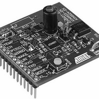
BOARD DEMO LIN SBC FOR ATA6622
Manufacturer
Atmel
Specifications of ATA6622-EK
Main Purpose
Interface, LIN
Embedded
Yes, MCU, 8-Bit
Utilized Ic / Part
ATA6622
Primary Attributes
LIN-SBC (System-Basis-Chip) Transceiver, LIN 2.0, Voltage Regulator, Window Watchdog
Secondary Attributes
4 Power Modes: Pre-Normal, Normal, Sleep, Silent, 20-QFN
Lead Free Status / RoHS Status
Contains lead / RoHS non-compliant


3. Boosting the Voltage Regulator
For some applications there is a need for a higher current than the internal voltage regulator
can deliver (85mA). So it is possible to boost the maximum current by using an external NPN
transistor. On the development board there is already a placeholder for this part, into which
would fit, for example, the MJD31C in a D-PAK package. In addition to the transistor itself
there are two more components to be placed on the development board, the resistor R7 (3.3 )
and the electrolytic capacitor C4 (2.2µF). The jumper J1 has to be removed in this case.
Note that the output voltage is no longer short-circuit protected when boosting the output cur-
rent with an external NPN transistor.
The limiting parameter for the output current is the maximum power dissipation of the external
NPN transistor. In the version at this stage the thermal resistance of the MJD31C soldered on
the minimum pad size is 80K/W, meaning the maximum possible output current in the case of
V
= 12V is approximately 230mA at room temperature. It is not recommended to exceed this
S
limit, because the transistor could be damaged as a result of overtemperature. If a higher out-
put current is required, additional cooling of the external transistor has to be ensured (see
Figure
3-2,
Figure 3-3
and
Figure 3-4 on page
9).
Figure 3-1.
Boosting the Voltage Regulator
Atmel ATA6621/22/24/26
8
4970B–AUTO–03/11
Related parts for ATA6622-EK
Image
Part Number
Description
Manufacturer
Datasheet
Request
R

Part Number:
Description:
TXRX LIN BUS REG WATCHDOG 20-QFN
Manufacturer:
Atmel
Datasheet:
Part Number:
Description:
TXRX LIN BUS REG WATCHDOG 20-QFN
Manufacturer:
Atmel
Datasheet:

Part Number:
Description:
LIN Bus Transceiver with 3.3V (5V) Regulator and Watchdog
Manufacturer:
ATMEL Corporation
Datasheet:
Part Number:
Description:
(ATA6622 - ATA6626) LIN Bus Transceiver
Manufacturer:
ATMEL Corporation
Datasheet:

Part Number:
Description:
DEV KIT FOR AVR/AVR32
Manufacturer:
Atmel
Datasheet:
Part Number:
Description:
INTERVAL AND WIPE/WASH WIPER CONTROL IC WITH DELAY
Manufacturer:
ATMEL Corporation
Datasheet:
Part Number:
Description:
Low-Voltage Voice-Switched IC for Hands-Free Operation
Manufacturer:
ATMEL Corporation
Datasheet:
Part Number:
Description:
MONOLITHIC INTEGRATED FEATUREPHONE CIRCUIT
Manufacturer:
ATMEL Corporation
Datasheet:
Part Number:
Description:
AM-FM Receiver IC U4255BM-M
Manufacturer:
ATMEL Corporation
Datasheet:
Part Number:
Description:
Monolithic Integrated Feature Phone Circuit
Manufacturer:
ATMEL Corporation
Datasheet:
Part Number:
Description:
Multistandard Video-IF and Quasi Parallel Sound Processing
Manufacturer:
ATMEL Corporation
Datasheet:
Part Number:
Description:
High-performance EE PLD
Manufacturer:
ATMEL Corporation
Datasheet: