MCP215X/40EV-DB Microchip Technology, MCP215X/40EV-DB Datasheet - Page 76
MCP215X/40EV-DB
Manufacturer Part Number
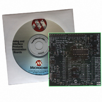
MCP215X/40EV-DB
Description
BOARD DEMO FOR MCP215X/40
Manufacturer
Microchip Technology
Datasheet
1.MCP215X40EV-DB.pdf
(94 pages)
Specifications of MCP215X/40EV-DB
Main Purpose
Interface, IrDA
Embedded
Yes, MCU, 8-Bit
Utilized Ic / Part
MCP2150, MCP2155, MCP2140
Primary Attributes
PICDEM™ Demo Board Interface
Processor To Be Evaluated
MCP21x
Interface Type
UART
Lead Free Status / RoHS Status
Contains lead / RoHS non-compliant
Secondary Attributes
-
Lead Free Status / RoHS Status
Lead free / RoHS Compliant, Contains lead / RoHS non-compliant
Available stocks
Company
Part Number
Manufacturer
Quantity
Price
Company:

Part Number:
MCP215X/40EV-DB
Manufacturer:
MICROCHIP
Quantity:
12 000


TABLE E-3:
DS51591A-page 72
1
2
3
4
5
6
7
8
9
10
11
Step Action
Place both devices on a flat surface about 25 cm (10”)
apart, and with the IR ports facing each other.
On the System #1 Unit (IR Dongle):
Connect Serial to IR dongle to PC. Ensure that device
supports the IrCOMM 9-wire “cooked” service class.
On the PICDEM™ FS USB Demo Board plus
MCP215X/40 Developer’s Daughter Board:
Insert the MCP215X/40 Developer’s Daughter Board
into the PICDEM HPC Explorer Demo Board.
Ensure that the jumpers are configured as in
Figure E-6.
On the PICDEM FS USB Demo Board plus
MCP215X/40 Developer’s Daughter Board:
Apply power to the unit via the 9V power supply.
On the PICDEM FS USB Demo Board plus
MCP215X/40 Developer’s Daughter Board:
Depress and release the RESET Switch (S2 – MCLR).
On the PC:
Wait for the PC system tray shows an IR icon. Placing
the mouse over the icon will show the MCP2150
Device ID (“Generic IrDA
On the PC:
Open the HyperTerminal
Primary Device (such as COM 7).
Ensure that the window indicates that the
HyperTerminal program is connected.
On the PC:
In the HyperTerminal program window, type an “a”.
On the PC:
Type some additional alpha characters into the
HyperTerminal program window.
Step 8 through Step 9 may be repeated.
On the PC:
“Disconnect” the HyperTerminal
the Primary Device (such as COM 7).
DEMO #2 STEPS
®
®
”).
program window for the
®
program window for
—
Result
—
—
—
On the PICDEM FS USB Demo Board plus
MCP215X/40 Developer’s Daughter Board:
The green power LED (D) will turn on.
—
—
On the PICDEM FS USB Demo Board plus
MCP215X/40 Developer’s Daughter Board:
The “IR Link” LED will turn on and the “CTS” LED will
strobe rapidly and then return to the normal rate.
On the PC:
The system tray icon will change from a single IR icon
to two IR icons facing each other. An IR Link is now
established.
On the PC:
The HyperTerminal window will display an “aA”.
On the PC:
The typed alpha character will echo where the case
has changed; lowercase -> uppercase and
uppercase -> lowercase.
On the PC:
The IR icon in the system tray will show that the link
has been disconnected.
Note:
The 00077 - HPC.asm program only
expects to receive 1 byte per IR packet.
© 2006 Microchip Technology Inc.
Related parts for MCP215X/40EV-DB
Image
Part Number
Description
Manufacturer
Datasheet
Request
R

Part Number:
Description:
Manufacturer:
Microchip Technology Inc.
Datasheet:
Part Number:
Description:
Manufacturer:
Microchip Technology Inc.
Datasheet:
Part Number:
Description:
Manufacturer:
Microchip Technology Inc.
Datasheet:
Part Number:
Description:
Manufacturer:
Microchip Technology Inc.
Datasheet:
Part Number:
Description:
Manufacturer:
Microchip Technology Inc.
Datasheet:
Part Number:
Description:
Manufacturer:
Microchip Technology Inc.
Datasheet:
Part Number:
Description:
Manufacturer:
Microchip Technology Inc.
Datasheet:
Part Number:
Description:
Manufacturer:
Microchip Technology Inc.
Datasheet: