MCP215X/40EV-DB Microchip Technology, MCP215X/40EV-DB Datasheet - Page 69
MCP215X/40EV-DB
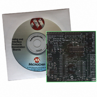
Manufacturer Part Number
MCP215X/40EV-DB
Description
BOARD DEMO FOR MCP215X/40
Manufacturer
Microchip Technology
Datasheet
1.MCP215X40EV-DB.pdf
(94 pages)
Specifications of MCP215X/40EV-DB
Main Purpose
Interface, IrDA
Embedded
Yes, MCU, 8-Bit
Utilized Ic / Part
MCP2150, MCP2155, MCP2140
Primary Attributes
PICDEM™ Demo Board Interface
Processor To Be Evaluated
MCP21x
Interface Type
UART
Lead Free Status / RoHS Status
Contains lead / RoHS non-compliant
Secondary Attributes
-
Lead Free Status / RoHS Status
Lead free / RoHS Compliant, Contains lead / RoHS non-compliant
Available stocks
Company
Part Number
Manufacturer
Quantity
Price
Company:

Part Number:
MCP215X/40EV-DB
Manufacturer:
MICROCHIP
Quantity:
12 000


E.1
FIGURE E-1:
© 2006 Microchip Technology Inc.
Appendix E. Using the MCP215X/40 Developer’s Daughter
Note 1:
DEMONSTRATION WITH THE PICDEM FS USB DEMO BOARD
Board with the PICDEM™ FS USB Demo Board
2:
HyperTerminal
Program Window A
(to IrDA
The PC may be a notebook with an integrated IR port.
Only required if data is communicated with the PC.
Some program modes “respond” to received data (data not sent to PC).
HyperTerminal
Program Window B
(Com 1)
®
To perform a demonstration of the MCP215X/40 Developer’s Daughter Board, two
systems are needed. A Primary Device and a Secondary Device (the embedded
system).
The embedded system (Secondary Device) is a MCP215X/40 Developer’s Daughter
Board (MCP212XEV-DB) plus the PICDEM™ FS USB Demo Board (DM183022).
The Primary Device is either a PC with IR Port (or IR Dongle) or a PDA.
There are four presentations of running the demos. These are:
1. Appendix D.1.2 “PC Demos using HyperTerminal”.
2. Appendix D.1.3 “Palm PDA Demo using the AN888 Application Program”.
3. Appendix D.1.4 “Pocket PC PDA Demo using the AN926 Application
4. Appendix D.1.5 “Window XP PC with an IrDA Standard Port Demo using the
The PC Demos using HyperTerminal shows all three PICDEM FS USB Demo Board
program modes, while those using the Application Note programs only show the Data
Logger (250 Byte) program mode. The steps to configure HyperTerminal is shown in
Appendix F. “Configuring the HyperTerminal
Figure E-1 shows a block diagram of a PC based demonstration system.
SYSTEM BLOCK DIAGRAM
Dongle)
Note:
Program”.
AN941 Application Program”.
®
(1)
If the MCP215X/40 Developer’s Daughter Board PCB is Rev 2, refer to
E.2 “MCP215X/40 Developer’s Daughter Board PCB Rev 2 Errata”.
This also shows how to determine board revision.
DAUGHTER BOARD USER’S GUIDE
System #1
Serial (UART or USB)
to IrDA Dongle
MCP215X/40 DEVELOPER’S
(1)
®
Program”.
System #2
PICDEM™ HPC
Explorer Demo Board plus
MCP215X/40 Developer’s
Daughter Board
DS51591A-page 65
Com 1
(2)
Related parts for MCP215X/40EV-DB
Image
Part Number
Description
Manufacturer
Datasheet
Request
R

Part Number:
Description:
Manufacturer:
Microchip Technology Inc.
Datasheet:
Part Number:
Description:
Manufacturer:
Microchip Technology Inc.
Datasheet:
Part Number:
Description:
Manufacturer:
Microchip Technology Inc.
Datasheet:
Part Number:
Description:
Manufacturer:
Microchip Technology Inc.
Datasheet:
Part Number:
Description:
Manufacturer:
Microchip Technology Inc.
Datasheet:
Part Number:
Description:
Manufacturer:
Microchip Technology Inc.
Datasheet:
Part Number:
Description:
Manufacturer:
Microchip Technology Inc.
Datasheet:
Part Number:
Description:
Manufacturer:
Microchip Technology Inc.
Datasheet: