MCP215X/40EV-DB Microchip Technology, MCP215X/40EV-DB Datasheet - Page 67
MCP215X/40EV-DB
Manufacturer Part Number
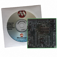
MCP215X/40EV-DB
Description
BOARD DEMO FOR MCP215X/40
Manufacturer
Microchip Technology
Datasheet
1.MCP215X40EV-DB.pdf
(94 pages)
Specifications of MCP215X/40EV-DB
Main Purpose
Interface, IrDA
Embedded
Yes, MCU, 8-Bit
Utilized Ic / Part
MCP2150, MCP2155, MCP2140
Primary Attributes
PICDEM™ Demo Board Interface
Processor To Be Evaluated
MCP21x
Interface Type
UART
Lead Free Status / RoHS Status
Contains lead / RoHS non-compliant
Secondary Attributes
-
Lead Free Status / RoHS Status
Lead free / RoHS Compliant, Contains lead / RoHS non-compliant
Available stocks
Company
Part Number
Manufacturer
Quantity
Price
Company:

Part Number:
MCP215X/40EV-DB
Manufacturer:
MICROCHIP
Quantity:
12 000


TABLE D-7:
© 2006 Microchip Technology Inc.
1
2
3
4
5
6
7
8
9
Step Action
Place both devices on a flat surface about 25 cm (10”)
apart, with the IR ports facing each other.
On the PICDEM™ HPC Explorer Demo Board plus
MCP215X/40 Developer’s Daughter Board:
Ensure that jumpers are configured as in Figure D-7.
On the PC:
Run the IrDA Demo.exe program.
On the PICDEM HPC Explorer Demo Board plus
MCP215X/40 Developer’s Daughter Board:
Plug a 9V AC-to-DC power supply (such as those
supplied with some Microchip development tools) into
the 9V DC connection plug (J1).
On the PICDEM HPC Explorer Demo Board plus
MCP215X/40 Developer’s Daughter Board:
Depress the RESET switch.
On the PC:
If the PC is configured to show the IR icon in the
system tray, a single IR LED will be displayed.
Place the mouse cursor over this icon.
In the IrDA standard demo PC program window:
Depress and release the Connect button.
On the PC:
If the PC is configured to show the IR icon in the
system tray, the single IR LED icon will change to an
icon of two IR LEDs facing each other and talking.
Place the mouse cursor over this icon.
In the IrDA standard demo PC program window:
In the TX Data (ASCII) entry box, type in any number
(such as “5”).
250 BYTE S -> P DATA TRANSFER DEMO - WINDOWS
D.1.5.2
After saving the AN941 application program to your PC’s hard drive, the program needs
to be launched. This PC program communicates with the MCP215X/40 Developer’s
Daughter Board.
Table D-7 shows the steps to demonstrate the 250-byte S -> P Data Transfer program.
Using the MCP215X/40 Developer’s Daughter Board
RUNNING THE DEMOS USING THE APPLICATION NOTE 941
PROGRAM
with the PICDEM™ HPC Explorer Demo Board
Result
—
—
On the PC:
The program is searching for an IrDA
device.
On the PICDEM HPC Explorer Demo Board plus
MCP215X/40 Developer’s Daughter Board:
The green power LED (D9) will turn on
In the IrDA Demo PC program window:
The program should indicate that it has “found” an
IrDA standard device, called “Generic IrDA”.
On the PC:
The message “Generic IrDA is in range” will be
displayed, “Generic IrDA” is the device ID of the
MCP2150.
In the IrDA standard demo PC program window:
Once the connection is made, the program window
will be updated to show that the Connect button now
is called the Disconnect button.
On the PICDEM HPC Explorer Demo Board plus
MCP215X/40 Developer’s Daughter Board:
The “IR Link” LED will turn on and the “CTS” LED will
flash. This indicates that an IR link is established
between the PC and the demo board.
On the PC:
The message “Wireless link with Generic IrDA at
115200 bps” will be displayed. This shows that a link
is now established for data communication and that
the IR communication rate is 115200 bps, the baud
rate that was negotiated between the PC IrDA
standard hardware and the MCP2150.
—
®
XP
DS51591A-page 63
®
standard
Related parts for MCP215X/40EV-DB
Image
Part Number
Description
Manufacturer
Datasheet
Request
R

Part Number:
Description:
Manufacturer:
Microchip Technology Inc.
Datasheet:
Part Number:
Description:
Manufacturer:
Microchip Technology Inc.
Datasheet:
Part Number:
Description:
Manufacturer:
Microchip Technology Inc.
Datasheet:
Part Number:
Description:
Manufacturer:
Microchip Technology Inc.
Datasheet:
Part Number:
Description:
Manufacturer:
Microchip Technology Inc.
Datasheet:
Part Number:
Description:
Manufacturer:
Microchip Technology Inc.
Datasheet:
Part Number:
Description:
Manufacturer:
Microchip Technology Inc.
Datasheet:
Part Number:
Description:
Manufacturer:
Microchip Technology Inc.
Datasheet: