SI2401FS10-EVB Silicon Laboratories Inc, SI2401FS10-EVB Datasheet - Page 4
SI2401FS10-EVB
Manufacturer Part Number
SI2401FS10-EVB
Description
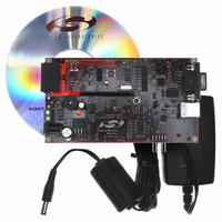
BOARD EVAL SI2401 UART INTERFACE
Manufacturer
Silicon Laboratories Inc
Series
ISOmodem®r
Datasheet
1.SI2401FS10-EVB.pdf
(32 pages)
Specifications of SI2401FS10-EVB
Main Purpose
Telecom, Modem
Embedded
No
Utilized Ic / Part
SI2401
Primary Attributes
Dual RJ-11 Connection to Phone Line, Audio Connector
Secondary Attributes
RS-232, TTL Serial & USB Interfaces
Processor To Be Evaluated
Si2401
Interface Type
RS-232, USB
Lead Free Status / RoHS Status
Contains lead / RoHS non-compliant
Lead Free Status / RoHS Status
Lead free / RoHS Compliant, Contains lead / RoHS non-compliant
Other names
336-1167


Si2401FS10-EVB
2.4. Power Requirements
The Si2401FS10-EVB has an onboard diode bridge,
filter capacitor, and voltage regulator. Power can be
supplied from any source capable of providing 7.5–13 V
dc or 7.5–13 V peak ac and at least 100 mA. (Additional
current may be required if a speaker is connected for
monitoring call progress tones.) Power may be applied
to the Si2401FS10-EVB through the screw terminals
(J3) or the 2 mm power jack (J4). The onboard full-wave
rectifier and filter ensure that the correct polarity is
applied to the Si2401FS10-EVB. Daughter card power
is supplied through voltage regulator U2 and is factory-
set at 3.3 V. Power is also supplied by the USB cable
and can be used regardless of whether the modem is
configured for the USB, RS-232, or direct interface
mode. Daughter card current can be measured by
connecting an ammeter between JP7 pins 1 and 2.
These pins must always be connected. Failure to
connect pins 1 and 2 of JP7 through either a jumper or a
low-impedance ammeter may result in damage to the
Si2401FS10-EVB.
2.5. Terminal and Line Connections
The Si2401 can be tested as a standard serial data
modem by connecting the Si2401FS10-EVB to a
personal computer or other data terminal equipment
(DTE), phone line, and power. Connect a PC, RS-232,
or USB interface to the Si2401FS10-EVB with the
appropriate cable. The RS-232 transceivers on the EVB
can communicate with the DTE at rates of up to 1 Mbps.
Any standard terminal program, such as HyperTerminal
or ProComm, running on a PC can communicate with
the Si2401FS10-EVB. Configure the terminal emulation
program to 2400 bps, 8 data bits, no parity, one stop bit,
and hardware flow control. Also, be sure to disable
linefeeds with carriage returns. Connect the RJ-11 jack
on the Si2401FS10-EVB to an analog phone line or
telephone line simulator, such as a Teltone TLS 5.
2.6. Making Connections
With the terminal program properly configured and
running, apply power to the Si2401FS10-EVB. Type
“AT<CR>”, and the modem should return “O” indicating
the modem is working in the command mode and
communicating with the terminal. If the “O” response is
not received, try resetting the modem by pressing the
manual reset switch (S1); then type “AT<CR>” again.
To take the modem off-hook, type “ATDT<CR>.” The
modem should go to the off-hook state, draw loop
current, and respond with a “t”, indicating a dial tone
detection. Typing any characters makes the modem
hang up (go on-hook) and stop drawing loop current.
4
Rev. 1.1
To make a modem connection, type “ATDT(called
modem phone number)<CR>.” Once the connection is
established, a “c” message appears, indicating the two
modems are in the data mode and communicating.
Typing on one terminal should appear on the other
terminal. To return to the command mode without
interrupting the connection between the two modems,
type “+++.” Approximately two seconds later, “O” will
appear. The modem is now in command mode and will
accept “AT” commands. To return to data mode, type
“ATO.” The modem resumes the data connection and
no longer accepts AT commands. Type “ATH” to
terminate the data connection.
3. Si2401FS10-EVB Functional
The Si2401FS10-EVB is a multipurpose evaluation
system. The modem daughter card illustrates the small
size and small number of components required to
implement an entire controller-based modem with
global telecommunications compatibility. The daughter
card can be used independently of, or in conjunction
with, the motherboard. The motherboard adds features
that enhance the ease of evaluating the many
capabilities of the Si2401 ISOmodem
3.1. Motherboard
The motherboard provides a convenient interface to the
Si2401DC (daughter card). The versatile power supply
allows for a wide range of ac and dc voltages to power
the board. RS-232 transceivers and a DB9 connector
allow the Si2401FS10-EVB to be easily connected to a
PC or other terminal device. Jumper options allow direct
access to the LVCMOS/TTL level serial inputs to the
Si2401, bypassing the RS-232 transceivers or USB
interface. This is particularly useful for directly
connecting the Si2401 to embedded systems.
The Si24xxFS10-EVB motherboard connects to the
daughter card through two connectors, JP1 and JP2.
JP1 is an 8x2 socket providing connection to all Si2401
digital signals and regulated 3.3 V power for the Si2401.
The Si2401 digital signals appearing at JP1 (daughter
card interface) are LVCMOS- and TTL-compatible. The
Si2401DC must be powered by 3.3 V. The motherboard
is factory-configured for 3.3 V with JP7 pins 1 and 2.
JP2 is a 4x1 socket providing connection between the
daughter card and the RJ-11 phone jack.
Description
®
.
Related parts for SI2401FS10-EVB
Image
Part Number
Description
Manufacturer
Datasheet
Request
R

Part Number:
Description:
IC ISOMODEM SYSTEM-SIDE 16SOIC
Manufacturer:
Silicon Laboratories Inc
Datasheet:

Part Number:
Description:
Telecom Line Management ICs 2400b/s System Side 3rd Gen DAA Tech
Manufacturer:
Silicon Laboratories Inc
Datasheet:


Part Number:
Description:
V.22bis Isomodem With Integrated Global Daa
Manufacturer:
Silicon Laboratories
Datasheet:

Part Number:
Description:
SMD/C°/SINGLE-ENDED OUTPUT SILICON OSCILLATOR
Manufacturer:
Silicon Laboratories Inc
Part Number:
Description:
Manufacturer:
Silicon Laboratories Inc
Datasheet:
Part Number:
Description:
N/A N/A/SI4010 AES KEYFOB DEMO WITH LCD RX
Manufacturer:
Silicon Laboratories Inc
Datasheet:
Part Number:
Description:
N/A N/A/SI4010 SIMPLIFIED KEY FOB DEMO WITH LED RX
Manufacturer:
Silicon Laboratories Inc
Datasheet:
Part Number:
Description:
N/A/-40 TO 85 OC/EZLINK MODULE; F930/4432 HIGH BAND (REV E/B1)
Manufacturer:
Silicon Laboratories Inc
Part Number:
Description:
EZLink Module; F930/4432 Low Band (rev e/B1)
Manufacturer:
Silicon Laboratories Inc
Part Number:
Description:
I°/4460 10 DBM RADIO TEST CARD 434 MHZ
Manufacturer:
Silicon Laboratories Inc
Part Number:
Description:
I°/4461 14 DBM RADIO TEST CARD 868 MHZ
Manufacturer:
Silicon Laboratories Inc
Part Number:
Description:
I°/4463 20 DBM RFSWITCH RADIO TEST CARD 460 MHZ
Manufacturer:
Silicon Laboratories Inc
Part Number:
Description:
I°/4463 20 DBM RADIO TEST CARD 868 MHZ
Manufacturer:
Silicon Laboratories Inc