SI2401FS10-EVB Silicon Laboratories Inc, SI2401FS10-EVB Datasheet
SI2401FS10-EVB
Specifications of SI2401FS10-EVB


Related parts for SI2401FS10-EVB


SI2401FS10-EVB Summary of contents
Page 1
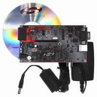
... The Si2401FS10-EVB provides an RJ-11 jack for interfacing to the phone line and a DB9 or USB connector for interfacing the Si2401FS10-EVB data terminal serial port. This allows the Si2401 ISOmodem to operate as a serial modem for straightforward evaluation. To evaluate the Si2401 ISOmodem in an embedded system, the daughter card can be used independently or with the motherboard ...
Page 2
... Si2401FS10-EVB Quick Start—RS-232 Interface 1. Set jumpers according to Figure 1. 2. Connect: DB COM 1 (with a pass-through cable). RJ-11 to phone line or test box. the adaptor (or USB cable). ...
Page 3
... Jumper Settings Check all jumper settings on the Si2401FS10-EVB before applying power. Figure 1 shows the standard factory jumper settings. These settings configure the Si2401FS10-EVB for RS-232 serial operation. Any standard terminal program configured to communicate through a PC COM port can be used to communicate with the Si2401FS10- EVB ...
Page 4
... Si2401DC (daughter card). The versatile power supply allows for a wide range of ac and dc voltages to power the board. RS-232 transceivers and a DB9 connector allow the Si2401FS10-EVB to be easily connected other terminal device. Jumper options allow direct access to the LVCMOS/TTL level serial inputs to the Si2401, bypassing the RS-232 transceivers or USB interface ...
Page 5
... used in conjunction with U6, pressing S1 activates the reset monitor in the DS1818 and produces a 220 ms active low reset pulse. 3.1.5. Interface Selection The serial interface of the Si2401FS10-EVB can be ac. The connected to a computer terminal, embedded system, PEAK or any other Data Terminal Equipment (DTE) via a standard RS-232 interface, USB interface, or direct TTL serial interface ...
Page 6
... Si2401FS10-EVB J1 Name Carrier Detect Received Data Transmit Data Data Terminal Ready Signal Ground Data Set Ready Ready to Send Clear to Send Ring Indicator Notes: 1. JP6 + JP5 jumper option. 2. JP6 Jumper option. 3. DSR connected to DTR at J1. 3.1.7. USB Interface The USB cable connects the motherboard and provides both data and power ...
Page 7
... PC board capacitance and the tolerance of loading capacitors, must also be taken into account. 3.2.3. Protection The Si2401FS10-EVB meets or exceeds all FCC and international PTT requirements and recommendations for high-voltage surge and isolation testing without any modification. The protection/isolation circuitry includes C1, C2, C8, C9, FB1, FB2, and RV1. The PCB layout is also a key “ ...
Page 8
... Si2401FS10-EVB 1 2 VD3 GND 3 VD3.3 5 Rev. 1.1 VDB 19 VDA 7 GND 20 GND 6 ...
Page 9
... Si2401FS10-EVB SC 11 IGND 15 Rev. 1.1 9 ...
Page 10
... Si2401FS10-EVB 5. Bill of Materials: Si2401 Daughter Card Item Quantity Reference 1 2 C2, C5,C6,C50 C9, C10 8 2 C41,C40 9 1 C51 10 1 C54 FB2,FB1 Ferrite Bead 13 1 FB5 Ferrite Bead 14 1 JP1 HEADER 8X2 15 1 JP2 4X1 Header_0 16 2 Q3, Q4, RV1 R5, R8, R10 28 1 R11 29 4 R12,R13,R15,R16 ...
Page 11
... EESD_H EECLK_H EECS_H Rev. 1.1 Si2401FS10-EVB RESET PUSHBUTTON SW 11 ...
Page 12
... Si2401FS10-EVB 12 Rev. 1.1 ...
Page 13
... GND Rev. 1.1 Si2401FS10-EVB 13 ...
Page 14
... Si2401FS10-EVB VCC 26 14 GND 2 Rev. 1.1 ...
Page 15
... S 10 3B2 13 4B2 R18 74CBT3257/SO 10k 1B1 2B1 3B1 4B1 1B2 2B2 S 10 3B2 13 4B2 74CBT3257/SO Figure 11. UART Mux Schematic Rev. 1.1 Si2401FS10-EVB C24 1 2 SPEAKER C23 100 uF 0 TXD_M RXD_M RTS_M CTS_M S O\E\ R19 10k DTR_M DSR_M CD_M RI_M 15 ...
Page 16
... Si2401FS10-EVB USB_VCC U11 1 5 USB USB+ GMS05F VBUS 7 REGIN SUSPEND 6 VDD C29 C31 + SUSPEND 1 GND CP2101/02 Figure 12. USB Interface Schematic Rev. 1.1 R20 TP19 4 RST 12 11 RI_U 2 CD_U RI 1 DCD 28 DTR_U DTR 27 DSR 26 TXD DSR_U 25 RXD 24 TXD_U RTS 23 CTS RXD_U RTS_R ...
Page 17
... CONN1[6040] CONN1[6040] 7805 TO-220-LD SO8 DS1818 SOT-23 MAX3237 SOP65X780-28N CP2101/02 28-pin MLP SOP65X780-16N DIP8-SKT OP-AMP SO8 GMS05F SOT-23-5N Rev. 1.1 Si2401FS10-EVB Dielectric Manufacturer Number Manufacturer Tant TA010TCM105-KAL Venkel X7R C0805C471J5GACTU TTI X7R C0603X7R160-103KNE Venkel Electrolytic UVX1E471MPA NIC Components X7R C0805X7R250-104KNE Venkel ...
Page 18
... Si2401FS10-EVB 18 Rev. 1.1 ...
Page 19
... Si2401FS10-EVB Rev. 1.1 19 ...
Page 20
... Si2401FS10-EVB 20 Rev. 1.1 ...
Page 21
... Si2401FS10-EVB Rev. 1.1 21 ...
Page 22
... Si2401FS10-EVB 22 Rev. 1.1 ...
Page 23
... Si2401FS10-EVB Rev. 1.1 23 ...
Page 24
... Si2401FS10-EVB 24 Rev. 1.1 ...
Page 25
... Si2401FS10-EVB Rev. 1.1 25 ...
Page 26
... Si2401FS10-EVB 26 Rev. 1.1 ...
Page 27
... Si2401FS10-EVB Rev. 1.1 27 ...
Page 28
... Si2401FS10-EVB 28 Rev. 1.1 ...
Page 29
... Si2401FS10-EVB Rev. 1.1 29 ...
Page 30
... Si2401FS10-EVB 7. Complete Design Package (see sales representative for details) Silicon Laboratories can provide a complete design package of the Si2401FS10-EVB including the following: OrCad Schematics Gerber Files BOM Documentation Please contact your local sales representative or Silicon Laboratories headquarter sales for ordering information. 30 Rev. 1.1 ...
Page 31
... Changed from Rev.3.1 to Rev.3.2 Motherboard. Revision 0.9 to Revision 1.0 Changed from Rev.1.1 to Rev.1.2 Daughter Card. Revision 1.0 to Revision 1.1 Updated "Introduction‚" on page 2. Updated "Si2401FS10-EVB Quick Start—RS-232 Interface‚" on page 2. Updated "Si2401 FS10-EVB Quick Start—USB Interface‚" on page 2. Si2401FS10-EVB Rev ...
Page 32
... Si2401FS10-EVB C I ONTACT NFORMATION Silicon Laboratories Inc. 4635 Boston Lane Austin, TX 78735 Tel: 1+(512) 416-8500 Fax: 1+(512) 416-9669 Toll Free: 1+(877) 444-3032 Email: ISOinfo@silabs.com Internet: www.silabs.com The information in this document is believed to be accurate in all respects at the time of publication but is subject to change without notice. ...