STEVAL-TLL005V1 STMicroelectronics, STEVAL-TLL005V1 Datasheet - Page 18
STEVAL-TLL005V1
Manufacturer Part Number
STEVAL-TLL005V1
Description
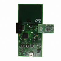
BOARD EVAL PWR FLASH STCF03/ST7
Manufacturer
STMicroelectronics
Datasheets
1.STCF03PNR.pdf
(35 pages)
2.STEVAL-TLL005V1.pdf
(4 pages)
3.STEVAL-TLL005V1.pdf
(10 pages)
Specifications of STEVAL-TLL005V1
Design Resources
STEVAL-TLL005V1 Bill of Materials
Main Purpose
Lighting, Camera Flash
Embedded
Yes, MCU, 8-Bit
Utilized Ic / Part
STCF03
Primary Attributes
Camera Flash, I2C Controlled, Flash and Torch Mode
Secondary Attributes
Li-Ion Battery, Battery Charger Circuit, GUI
Description/function
Flash Driver Evaluation Board
Core Chip
STCF03
Topology
Buck-Boost
No. Of Outputs
1
Dimming Control Type
I2C
Development Tool Type
Hardware - Eval/Demo Board
Supported Devices
STCF03 Device Type
For Use With
497-8431 - BOARD EVAL FLASH DRIVER STCF03
Lead Free Status / RoHS Status
Lead free / RoHS Compliant
For Use With/related Products
STCF03, ST7
Other names
497-8207


Introduction
7.10
Figure 10. Writing to multiple register with incremental addressing
7.11
18/35
A
A
A
R
R
R
S
S
S
T
T
T
T
T
T
M
M
M
S
S
S
B
B
B
ADDRESS
ADDRESS
ADDRESS
DEVICE
DEVICE
DEVICE
7 bits
7 bits
7 bits
The register address byte determines the first register in which the read or write operation
takes place. When the read or write operation is finished, the register address is
automatically increased.
Writing to multiple registers with incremental addressing
It would be unpractical to send several times the device address and the address of the
register when writing to multiple registers. STCF03 supports writing to multiple registers with
incremental addressing. When the data is written to a register, the address register is
automatically increased, so the next data can be sent without sending the device address
and the register address again. See
Reading from a single register
The reading operation starts with a START bit followed by the 7 bit device address of
STCF03. The 8
the address + R/W bit by an acknowledge pulse. The address of the register which should
be read is sent afterwards and confirmed again by an acknowledge pulse of STCF03 again.
Then the master generates a START bit again and sends the device address followed by the
R/W bit, which is 1 now. STCF03 confirms the receiving of the address + R/W bit by an
acknowledge pulse and starts to send the data to the master. No acknowledge pulse from
the master is required after receiving the data. Then the master generates a STOP bit to
terminate the communication. See
L
L
L
S
S
S
B
B
B
W
W
W
W
W
W
R
R
R
R
R
R
T
T
T
E
E
E
I
I
I
/
/
/
A
A
A
C
C
C
K
K
K
M
M
M
S
S
S
B
B
B
ADDRESS OF
ADDRESS OF
ADDRESS OF
REGISTER i
REGISTER i
REGISTER i
th
S
S
S
B
B
B
L
L
L
bit is the R/W bit, which is 0 in this case. STCF03 confirms the receiving of
A
A
A
A
A
A
C
C
C
C
C
C
K
K
K
K
K
K
M
M
M
M
M
M
S
S
S
S
S
S
B
B
B
B
B
B
DATA i
DATA i
DATA i
B
B
B
L
L
L
S
S
S
Doc ID 13169 Rev 7
A
A
A
C
C
C
K
K
K
M
M
M
S
S
S
B
B
B
Figure
SDA LINE
SDA LINE
DATA i+1
DATA i+1
DATA i+1
Figure 10
11.
L
L
L
S
S
S
B
B
B
A
A
A
C
C
C
K
K
K
M
M
M
S
S
S
B
B
B
below.
DATA i+2
DATA i+2
DATA i+2
B
B
B
L
L
L
S
S
S
A
A
A
C
C
C
K
K
K
M
M
M
S
S
S
B
B
B
DATA i+2
DATA i+2
DATA i+2
L
L
L
S
S
S
B
B
B
A
A
A
C
C
C
K
K
K
M
M
M
S
S
S
B
B
B
DATA i+n
DATA i+n
DATA i+n
L
L
L
S
S
S
B
B
B
STCF03
A
A
A
C
C
C
K
K
K
S
S
S
O
O
O
P
P
P
T
T
T
Related parts for STEVAL-TLL005V1
Image
Part Number
Description
Manufacturer
Datasheet
Request
R

Part Number:
Description:
BOARD EVAL FOR ST802RT1
Manufacturer:
STMicroelectronics
Datasheet:

Part Number:
Description:
EVAL BOARD 100 BASE T
Manufacturer:
STMicroelectronics
Datasheet:

Part Number:
Description:
BOARD ELECT FISCAL CASH REGISTER
Manufacturer:
STMicroelectronics
Datasheet:
Part Number:
Description:
BOARD EVAL FOR ST802RT1A
Manufacturer:
STMicroelectronics
Datasheet:

Part Number:
Description:
2 kW/100 V RF demonstration board for 3 T MRI based on the STAC4932B
Manufacturer:
STMICROELECTRONICS [STMicroelectronics]
Datasheet:

Part Number:
Description:
BOARD EVAL FOR MEMS SENSORS
Manufacturer:
STMicroelectronics
Datasheet:
Part Number:
Description:
EVALBOARD/STEVAL-ISV014V1
Manufacturer:
STMicroelectronics

Part Number:
Description:
BOARD EVAL FOR VACUUM CLEANER
Manufacturer:
STMicroelectronics
Datasheet:

Part Number:
Description:
KIT DEV STARTER ST10F276Z5
Manufacturer:
STMicroelectronics
Datasheet:

Part Number:
Description:
BOARD LED CTLR/DVR STLED316S
Manufacturer:
STMicroelectronics
Datasheet:
Part Number:
Description:
STMicroelectronics [RIPPLE-CARRY BINARY COUNTER/DIVIDERS]
Manufacturer:
STMicroelectronics
Datasheet:
Part Number:
Description:
STMicroelectronics [LIQUID-CRYSTAL DISPLAY DRIVERS]
Manufacturer:
STMicroelectronics
Datasheet:
Part Number:
Description:
BOARD EVAL FOR MEMS SENSORS
Manufacturer:
STMicroelectronics
Datasheet: