STEVAL-TLL005V1 STMicroelectronics, STEVAL-TLL005V1 Datasheet - Page 15
STEVAL-TLL005V1
Manufacturer Part Number
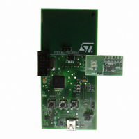
STEVAL-TLL005V1
Description
BOARD EVAL PWR FLASH STCF03/ST7
Manufacturer
STMicroelectronics
Datasheets
1.STCF03PNR.pdf
(35 pages)
2.STEVAL-TLL005V1.pdf
(4 pages)
3.STEVAL-TLL005V1.pdf
(10 pages)
Specifications of STEVAL-TLL005V1
Design Resources
STEVAL-TLL005V1 Bill of Materials
Main Purpose
Lighting, Camera Flash
Embedded
Yes, MCU, 8-Bit
Utilized Ic / Part
STCF03
Primary Attributes
Camera Flash, I2C Controlled, Flash and Torch Mode
Secondary Attributes
Li-Ion Battery, Battery Charger Circuit, GUI
Description/function
Flash Driver Evaluation Board
Core Chip
STCF03
Topology
Buck-Boost
No. Of Outputs
1
Dimming Control Type
I2C
Development Tool Type
Hardware - Eval/Demo Board
Supported Devices
STCF03 Device Type
For Use With
497-8431 - BOARD EVAL FLASH DRIVER STCF03
Lead Free Status / RoHS Status
Lead free / RoHS Compliant
For Use With/related Products
STCF03, ST7
Other names
497-8207


STCF03
7.3
7.4
Figure 5.
7.5
Figure 6.
I²C bus interface
Data transmission from the main microprocessor STCF03 and vice versa takes place
through the 2 wires I²C bus interface wires, consisting of the two lines SDA and SCL (pull-up
resistors to a positive supply voltage must be externally connected). The recommended
maximum voltage of these signals should be 3.0 V.
Data validity
As shown in
clock. The HIGH and LOW state of the data line can only change when the clock signal on
the SCL line is LOW.
Data validity on the I²C Bus
Start and stop conditions
Both DATA and CLOCK lines remain HIGH when the bus is not busy. As shown in
start condition is a HIGH to LOW transition of the SDA line while SCL is HIGH. The stop
condition is a LOW to HIGH transition of the SDA line while SCL is HIGH. A STOP condition
must be sent before each START condition.
Timing diagram on I²C Bus
Figure
5, the data on the SDA line must be stable during the high period of the
Doc ID 13169 Rev 7
Introduction
Figure 6
15/35
a
Related parts for STEVAL-TLL005V1
Image
Part Number
Description
Manufacturer
Datasheet
Request
R

Part Number:
Description:
BOARD EVAL FOR ST802RT1
Manufacturer:
STMicroelectronics
Datasheet:

Part Number:
Description:
EVAL BOARD 100 BASE T
Manufacturer:
STMicroelectronics
Datasheet:

Part Number:
Description:
BOARD ELECT FISCAL CASH REGISTER
Manufacturer:
STMicroelectronics
Datasheet:
Part Number:
Description:
BOARD EVAL FOR ST802RT1A
Manufacturer:
STMicroelectronics
Datasheet:

Part Number:
Description:
2 kW/100 V RF demonstration board for 3 T MRI based on the STAC4932B
Manufacturer:
STMICROELECTRONICS [STMicroelectronics]
Datasheet:

Part Number:
Description:
BOARD EVAL FOR MEMS SENSORS
Manufacturer:
STMicroelectronics
Datasheet:
Part Number:
Description:
EVALBOARD/STEVAL-ISV014V1
Manufacturer:
STMicroelectronics

Part Number:
Description:
BOARD EVAL FOR VACUUM CLEANER
Manufacturer:
STMicroelectronics
Datasheet:

Part Number:
Description:
KIT DEV STARTER ST10F276Z5
Manufacturer:
STMicroelectronics
Datasheet:

Part Number:
Description:
BOARD LED CTLR/DVR STLED316S
Manufacturer:
STMicroelectronics
Datasheet:
Part Number:
Description:
STMicroelectronics [RIPPLE-CARRY BINARY COUNTER/DIVIDERS]
Manufacturer:
STMicroelectronics
Datasheet:
Part Number:
Description:
STMicroelectronics [LIQUID-CRYSTAL DISPLAY DRIVERS]
Manufacturer:
STMicroelectronics
Datasheet:
Part Number:
Description:
BOARD EVAL FOR MEMS SENSORS
Manufacturer:
STMicroelectronics
Datasheet: