STEVAL-TLL005V1 STMicroelectronics, STEVAL-TLL005V1 Datasheet
STEVAL-TLL005V1
Specifications of STEVAL-TLL005V1


Related parts for STEVAL-TLL005V1


STEVAL-TLL005V1 Summary of contents
Page 1
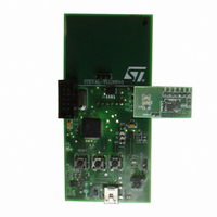
... STEVAL-TLL005V1 power flash demonstration board Introduction This document provides the basic settings and instructions for using the STEVAL-TLL005V1 power flash demonstration board based on the STCF03. The STCF03 is a high efficiency power supply solution to drive a single flash LED in camera phones, PDAs and other hand- held devices ...
Page 2
Contents Contents 1 Power supply . . . . . . . . . . . . . . . . . . . . . . . . . . . . . . . . . . . ...
Page 3
... UM0682 1 Power supply The STEVAL-TLL005V1 can be powered either by a mobile Li-Ion battery (battery mode external power supply (external power supply mode). 1.1 Battery mode To power the STEVAL-TLL005V1 by battery, perform the following steps: ● Connect the battery across header H5 ● Position the jumper across pins 2 (as shown in When the STEVAL-TLL005V1 is connected to the PC via USB, the battery begins charging automatically with a current of approximately 200 mA ...
Page 4
Power supply Figure 3. J2 connection details for external power supply mode 4/10 UM0682 AM01305v1 ...
Page 5
... To connect the demonstration board to a PC, first provide power to the board using one of the previously explained methods, then connect the USB cable. When connecting the STEVAL-TLL005V1 demonstration board to the PC for the first time, a prompt to install the driver will appear (the driver is included in the DVD). To install the driver, provide the path to stmcdc ...
Page 6
... Switches 3 Switches There are 3 switches on the STEVAL-TLL005V1: SW1, S1 and S2. 3.1 Switch SW1: reset switch The SW1 switch is used to reset the system. Pressing it once resets the microcontroller. 3.2 Switches S1and S2: configurable switches Switches S1 and S2 are configurable, allowing the user to define the glow pattern of the flash and auxiliary LED when the switches are pressed. The switches are configured through the GUI by pressing the “ ...
Page 7
UM0682 4 PIR sensor The PIR sensor detects nearby motion and provides the signal to the microcontroller. 4.1 Activating the PIR sensor The PIR sensor is activated by performing the following, in sequence: 1. Program the required pattern using the ...
Page 8
Starting up 5 Starting up Perform the following steps to start the system: 1. Connect the daughterboard to the motherboard using headers H2 and H3 2. Power up the board either through the external power supply or through a battery, ...
Page 9
UM0682 6 Revision history Table 1. Document revision history Date 02-Mar-2009 Revision 1 Initial release Revision history Changes 9/10 ...
Page 10
... Information in this document is provided solely in connection with ST products. STMicroelectronics NV and its subsidiaries (“ST”) reserve the right to make changes, corrections, modifications or improvements, to this document, and the products and services described herein at any time, without notice. All ST products are sold pursuant to ST’s terms and conditions of sale. ...