DM183021 Microchip Technology, DM183021 Datasheet - Page 33
DM183021
Manufacturer Part Number
DM183021
Description
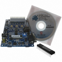
BOARD DEV PICDEM MC LV
Manufacturer
Microchip Technology
Series
PICDEM™r
Specifications of DM183021
Main Purpose
Power Management, Motor Control
Embedded
No
Utilized Ic / Part
PIC18F, dsPIC30F
Primary Attributes
Brushless DC (BLDC) Motors, 3-Phase, 1A, LIN, SPI, PWM Interface
Secondary Attributes
Graphical User Interface
Silicon Manufacturer
Microchip
Silicon Core Number
PIC18F2431, DsPIC30F3010
Core Architecture
PIC
Core Sub-architecture
PIC18F, PIC30F
Silicon Family Name
Piccolo
Lead Free Status / RoHS Status
Lead free / RoHS Compliant
Available stocks
Company
Part Number
Manufacturer
Quantity
Price
Company:

Part Number:
DM183021
Manufacturer:
Microchip Technology
Quantity:
135
Company:
Part Number:
DM183021
Manufacturer:
MICROCHIP
Quantity:
12 000


7.4
7.5
© 2006 Microchip Technology Inc.
USING THE PICDEM MC LV DEVELOPMENT BOARD FOR
HIGHER MOTOR VOLTAGE
USING THE PICDEM MC LV DEVELOPMENT BOARD FOR
LOWER MOTOR VOLTAGE
Using dsPIC DSCs to Run a Sensorless BLDC Motor
The PICDEM MC LV Development Board can be used to drive a motor at a voltage
higher than 24V, but not exceeding 36V. The new high voltage can be supplied to the
system at the Plus (+) and Minus (–) terminals on J9. For the sensorless algorithm to
work, the user will have to modify the resistor pairs to drive the same full-scale (2.4V)
and zero-cross (1.2V) voltages (see Section 7.3 “Sensorless Control of a BLDC
Motor”). Do not exceed the input voltage of the 15V regulator (VR2), which is typically
about 36V. Since the voltage drop across VR2 will increase substantially, make sure to
provide additional heat sinking for VR2.
The PICDEM MC LV Development Board can be used to drive a motor at a voltage
lower than 24V, but not below 10V. This voltage can be supplied to the system at the
Plus (+) and Minus (–) terminals on J9. Since the 15V regulator will no longer be used
to drive the MOSFET drivers, J18 should be provided with a shorting jumper. This
jumper connects the Plus (+) voltage directly to the MOSFET drivers. For the sensor-
less algorithm to work, the user will have to modify the resistor pairs to derive the same
full-scale (2.4V) and zero-crossing (1.2V) voltages (see Section 7.3 “Sensorless
Control of a BLDC Motor”). Make sure not to exceed the maximum input voltage of
the MOSFET drivers, U6, U8 and U9. This voltage is typically 20V.
DS51554B-page 29
Related parts for DM183021
Image
Part Number
Description
Manufacturer
Datasheet
Request
R

Part Number:
Description:
Manufacturer:
Microchip Technology Inc.
Datasheet:
Part Number:
Description:
Manufacturer:
Microchip Technology Inc.
Datasheet:
Part Number:
Description:
Manufacturer:
Microchip Technology Inc.
Datasheet:
Part Number:
Description:
Manufacturer:
Microchip Technology Inc.
Datasheet:
Part Number:
Description:
Manufacturer:
Microchip Technology Inc.
Datasheet:
Part Number:
Description:
Manufacturer:
Microchip Technology Inc.
Datasheet:
Part Number:
Description:
Manufacturer:
Microchip Technology Inc.
Datasheet:
Part Number:
Description:
Manufacturer:
Microchip Technology Inc.
Datasheet: